Plier

A technology of clamps and clamping teeth, which is applied in the direction of pliers, wrench, wrench, etc.

Active Publication Date: 2013-12-04
ENG CORP
View PDF1 Cites 0 Cited by
  • Summary
  • Abstract
  • Description
  • Claims
  • Application Information

AI Technical Summary

Problems solved by technology

but not without problems

Method used


Image

  • Plier
  • Plier
  • Plier

Examples


Embodiment

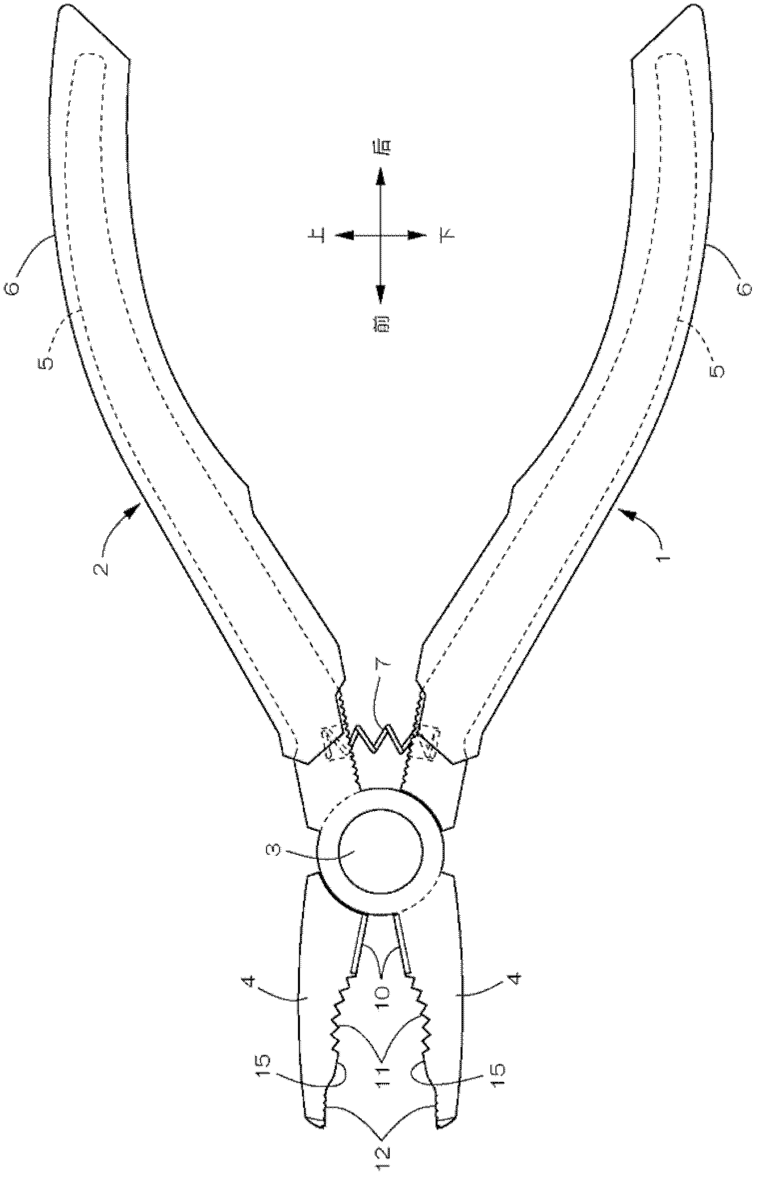
[0043] Figure 1 to Figure 8 It is an example which shows the pliers of this invention. exist figure 2 Among them, the clamp is configured by connecting the first arm 1 and the second arm 2 arranged in an X shape with a connecting shaft 3 so as to be relatively swingable. The two clamp arms 1, 2 are loaded by a compression coil (coil)-shaped expansion spring 7 for expansion. In addition, front and rear, left and right, and up and down in the present invention are based on figure 2 and Figure 4 The cross arrows shown are indicated by the text of front and rear, left and right, and up and down.

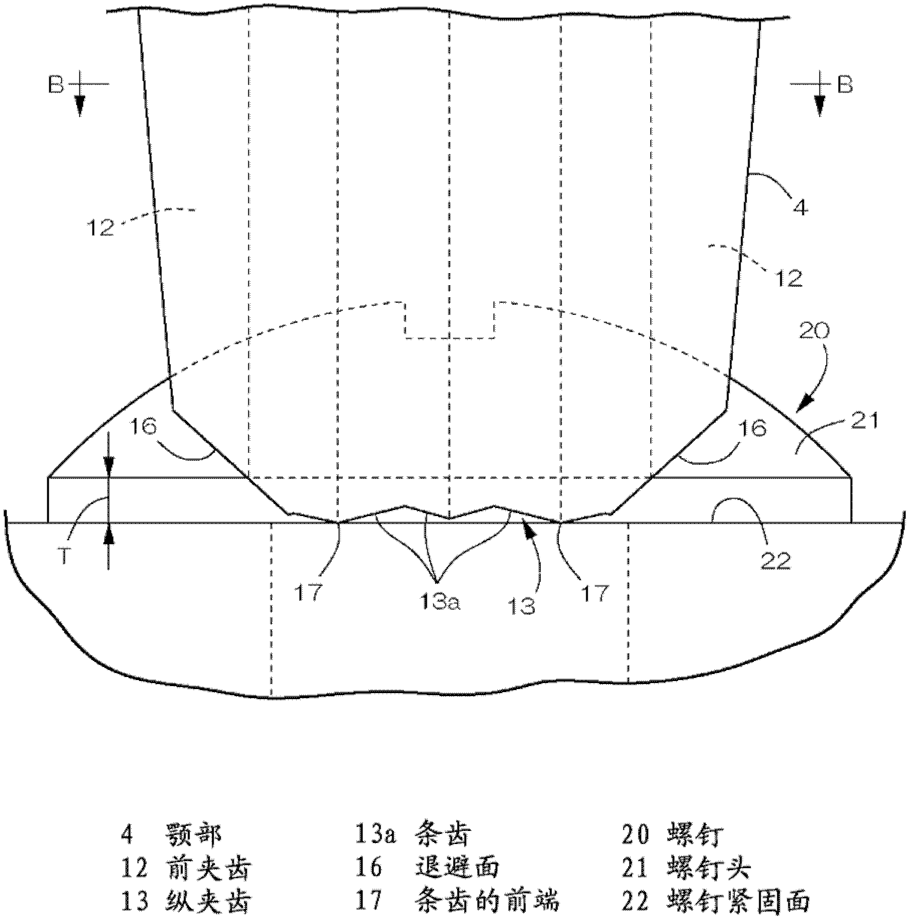
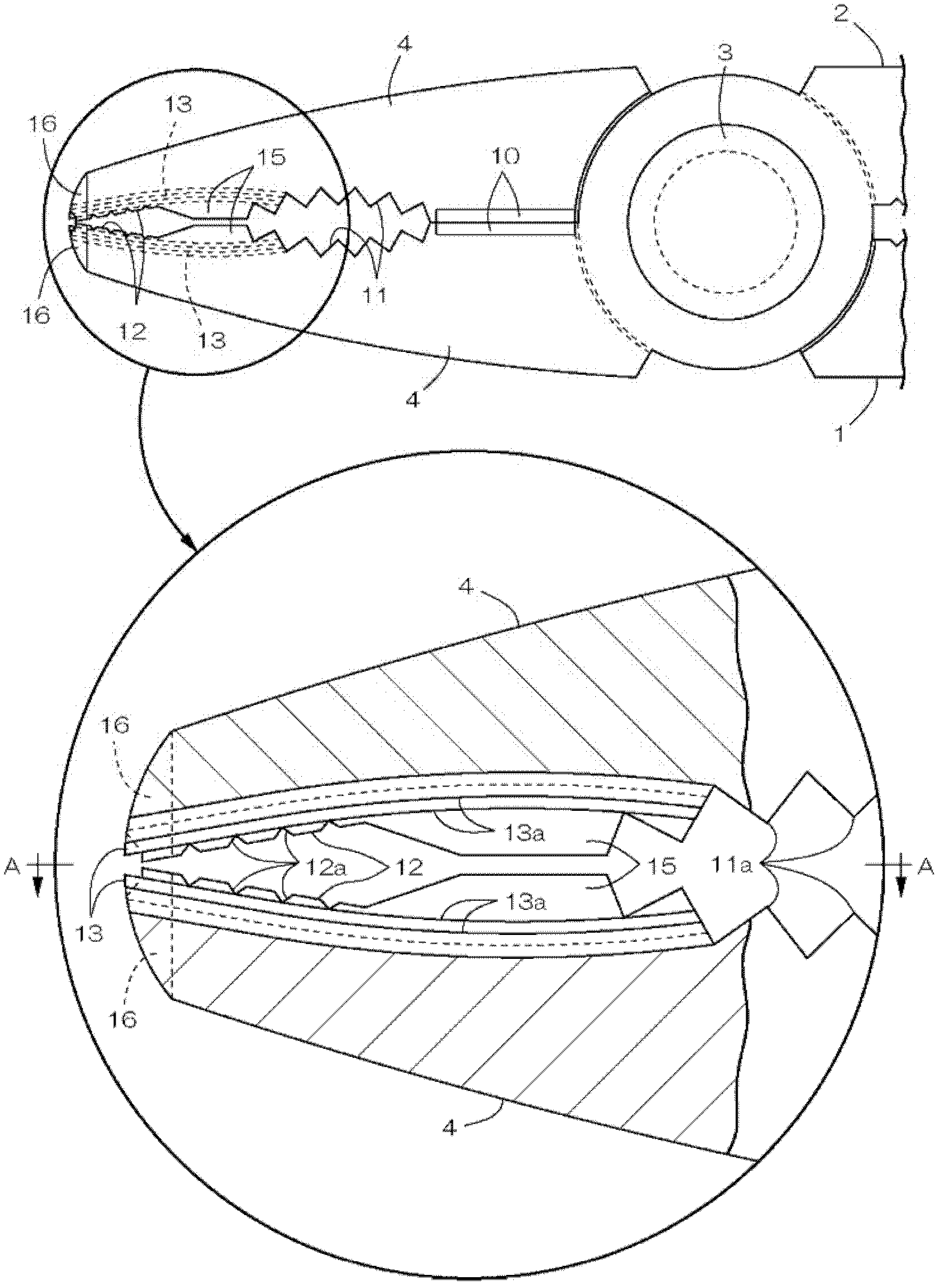
[0044] Each arm 1, 2 is made of a forged product having a jaw 4 at the front end and a handle 5 at the rear end, and the outer surface of the handle 5 is covered with a grip body 6 made of a plastic molded product. The above-mentioned expansion spring 7 is disposed near the intersection portion on the handle 5 side. On the facing surfaces of the respective jaws 4 , shear blades...


PUM


Abstract

The invention provides a pair of pliers capable of properly pinching a screw head and reliably removing a screw from an object to which the screw has been fastened even if the screw has small thickness of a peripheral face to be pinched between pinching teeth. The pair of pliers is formed by coupling a first arm 1 and a second arm 2 each having a jaw portion 4 and a grip 5 through a coupling shaft 3 in an X shape. Each of the jaw portions 4, 4 is provided on left and right sides of a front end thereof with flanks 16, 16 for preventing opposite corners of front ends of each of the jaw portions 4, 4 from coming in contact with a screw fastened face 22. Each of the jaw portions 4, 4 also comprises longitudinal pinching teeth 13, 13 capable of pinching the peripheral face of the screw head 21 so as to be recessed in opposed faces of the respective jaw portions 4, 4 between the left and right flanks 16, 16. Each of the longitudinal pinching teeth 13, 13 is formed by connecting, in shapes of peaks and troughs, a plurality of streak teeth 13a in a front-back direction. Due to the flanks 16, 16, front ends 17 of the streak teeth 13a initially collide with the screw fastened face 22, so that the longitudinal pinching teeth 13 can reliably pinch the peripheral face of the screw head 21.

Description

technical field [0001] The present invention relates to a plier, which is suitable for removing a small screw (hereinafter referred to as a screw) in a collapsed state due to rusting of the screw rod or deformation of an operation groove provided on the screw head from a fastened object. Background technique [0002] As such a pliers, there is known a pliers proposed by the present applicant (Patent Document 1). like Figure 11 As shown, the pliers are respectively provided with longitudinal teeth 34 , front teeth 35 , and rear teeth 36 on the opposing surfaces of the jaws 33 of a pair of clamping arms 31 and 32 crossed in an X shape. The longitudinal clamping teeth 34 clamp the peripheral surface of the screw head 41 along the screw rod. For example, if Figure 12 As shown, the vertical clamping teeth 34 are used when the screw fastening surface 42 is horizontal, and the peripheral surface of the screw head 41 is clamped in a state where the entire clamp is vertical. Bot...

Claims


Application Information

Patent Timeline
Patent Type & Authority Patents(China)
IPC IPC(8): B25B7/02
CPCB25B7/02B25B27/18B25B7/06B25B7/22B25B23/10
Inventor 川合真之介高崎充弘
Owner ENG CORP
Why Eureka
Try Eureka