Dry magnetic separator based on fluidization

A magnetic separator and fluidization technology, applied in the fields of magnetic separation, chemical instruments and methods, solid separation, etc., can solve the problems of poor feeding uniformity, difficulty in adjusting the feeding amount, and high consumption of magnetic materials, etc. Achieve the effect of small occupied space, reduced loss of magnetic materials, and no severe friction

Active Publication Date: 2013-07-17
CHINA UNIV OF MINING & TECH
View PDF7 Cites 1 Cited by
  • Summary
  • Abstract
  • Description
  • Claims
  • Application Information

AI Technical Summary

Problems solved by technology

Each magnetic separation drum can only magnetically separate the selected materials once, and the processing capacity should not be large, otherwise the amount of magnetic substances lost in the tailings will increase, and the structure of multiple magnetic separation drums can ensure the loss of magnetic substances in the tailings. Less, but will cause a substantial increase in equipment costs
Although the impeller feeder can control the feeding amount, it belongs to the form of pulsating feeding, and poor feeding uniformity will also increase the content of magnetic substances in the tailings; the vibrating feeding equipment not only takes up a lot of space, but also adjusts the feeding amount. Difficult and belongs to support equipment outside the magnetic separator
Since the separation efficiency is the highest under the magnetic separation drum, in the upper feeding mode, the wrap angle of the magnetic system is large, the consumption of magnetic materials is large, and the equipment cost is high.

Method used


Image

  • Dry magnetic separator based on fluidization
  • Dry magnetic separator based on fluidization
  • Dry magnetic separator based on fluidization

Examples


Embodiment Construction

[0012] An embodiment of the present invention will be further described below in conjunction with accompanying drawing:

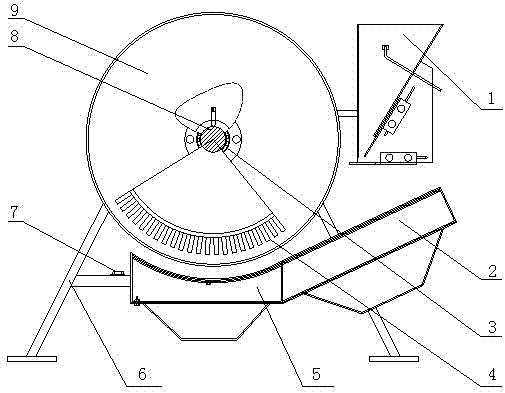
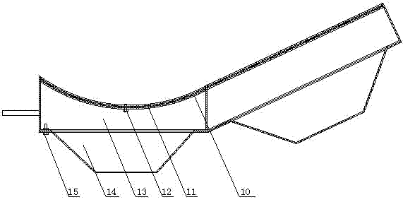
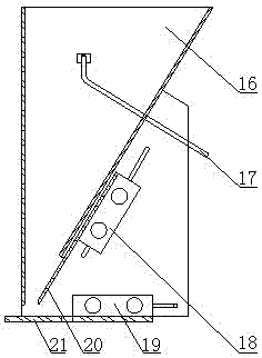
[0013] The fluidized dry magnetic separator based on the present invention is mainly composed of a feeding device 1, a magnetic separation drum 9, and a fluidized separation tank 5. The magnetic separation drum 9 is arranged obliquely, and the magnetic separation drum 9 is arranged obliquely. The angle is 3-10°. The below of the magnetic separation drum 9 is provided with a fluidized separation tank 5 having the same inclination angle, and the front end side of the magnetic separation drum 9 is provided with a feeding device 1 feeding to the front portion of the fluidized separation tank 5; The chemical separation tank 5 includes a base frame 13 on which an arc-shaped air distribution plate 10 with a filter cloth 11 sandwiched in the middle is provided. Groove 2, pedestal 13 bottom is provided with air chamber 14; Described feeding device 1 comprises wedge...


PUM


Abstract

The invention discloses a dry magnetic separator based on fluidization. The dry magnetic separator comprises an obliquely arranged magnetic separating drum; a fluidization separating tank arranged below the magnetic separating drum, wherein the fluidization separating tank is arranged with a same inclination angle with the magnetic separating drum; and a feeding apparatus arranged on the front end of the magnetic separating drum, wherein materials are delivered from the feeding apparatus to the front part of the fluidization separating tank. The fluidization separating tank comprises a base frame, a curved air distributing plate with a filter cloth interlayer arranged on the base frame, and an air chamber arranged on the lower part of the base frame. The feeding apparatus comprises a sphenoid buffering chamber; a feeding quantity controlling plate arranged at the port of the sphenoid buffering chamber, wherein the feeding quantity controlling plate is controlled by a quantity-controlling pin; and a feeding flashboard arranged on the bottom of the sphenoid buffering chamber, wherein the feeding flashboard is controlled by a switch pin. According to the invention, with the fluidization separating tank, the feeding material is fluidized. The feeding material is repeatedly separated in the magnetic separating drum while flowing. Feeding width is enlarged by using a fluidization rod. Feeding thickness is controlled by using the feeding quantity controlling plate, such that the feeding quantity in a unit time can be controlled. The dry magnetic separator provided by the invention is advantaged in compact structure, uniform feeding, adjustable feeding quantity, small space occupation, large processing quantity, high separation efficiency, and low cost.

Description

technical field [0001] The invention relates to a dry magnetic separator, which belongs to the field of mineral processing engineering, and is especially suitable for a dry magnetic separator based on fluidization in gas-solid two-phase flow. Background technique [0002] At present, dry magnetic separators used for magnetic and non-magnetic material separation include single magnetic separation drums, double magnetic separation drums and multiple magnetic separation drums. The feeding device uses an impeller feeder or a vibrating feeder. In the case of using the same amount of magnetic materials, these dry magnetic separators have a small processing capacity and a large loss of magnetic materials in the tailings compared with wet magnetic separators. Each magnetic separation drum can only magnetically separate the selected materials once, and the processing capacity should not be large, otherwise the amount of magnetic substances lost in the tailings will increase, and the...

Claims


Application Information

Patent Timeline
Patent Type & Authority Patents(China)
IPC IPC(8): B03C1/14
Inventor 赵跃民宋树磊骆振福梁春成段晨龙
Owner CHINA UNIV OF MINING & TECH
Why Eureka
Try Eureka