Clamping device

A technology of a clamping device and a driving device, applied in the field of machining, can solve the problems of low workpiece accuracy and workpiece error, and achieve the effects of long service life, high positioning accuracy and low friction force

Inactive Publication Date: 2012-03-07
CHANGZHOU SHENGFA BULB FACTORY
View PDF6 Cites 16 Cited by
  • Summary
  • Abstract
  • Description
  • Claims
  • Application Information

AI Technical Summary

Problems solved by technology

Since there is a certain difference in the size of the workpiece, and the distance between the tool machining center and the left fixture is fixed, there is a certain error between the processed workpieces, resulting in low precision of the workpiece

Method used


Image

  • Clamping device
  • Clamping device
  • Clamping device

Examples


Embodiment Construction

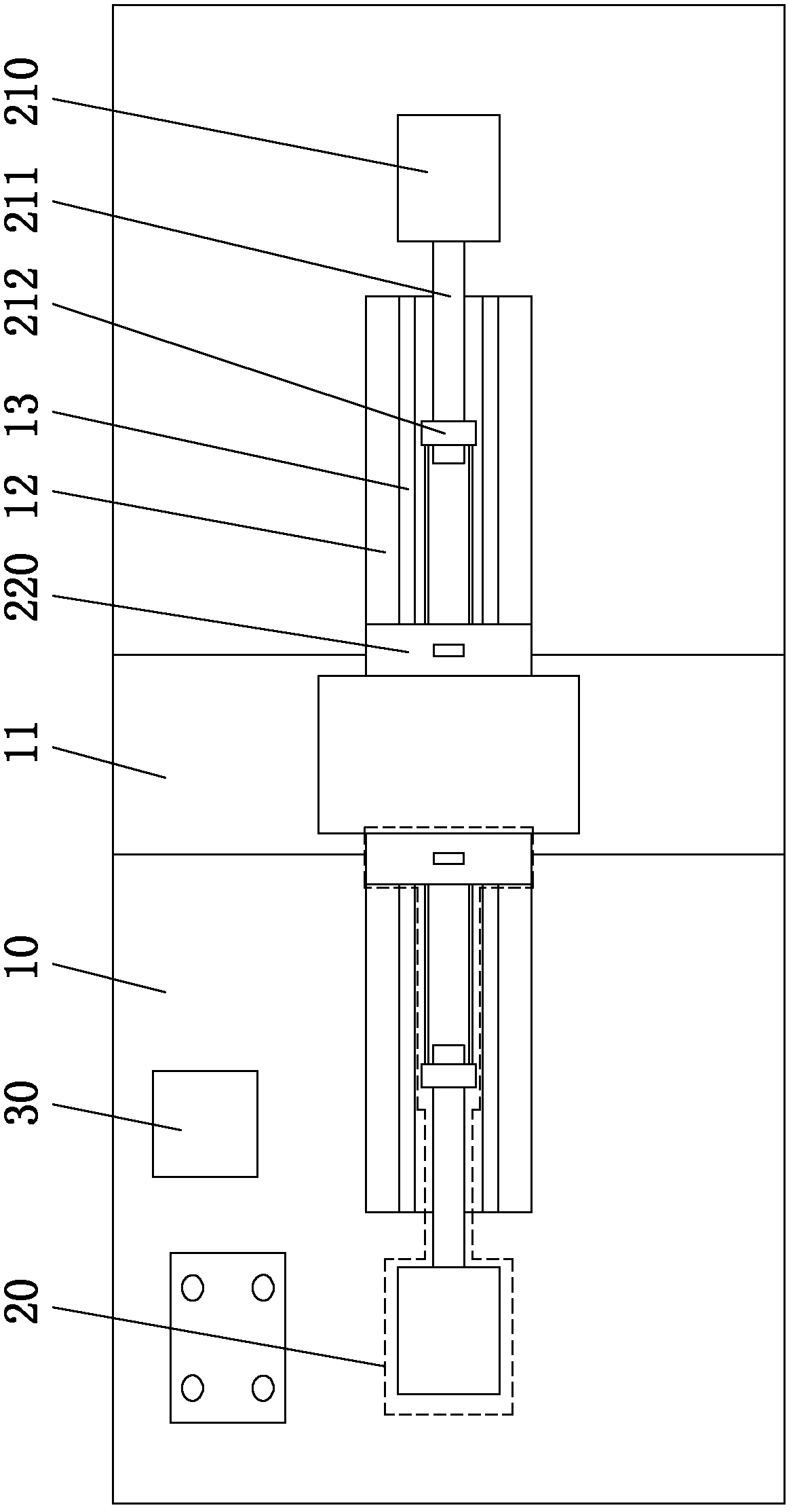
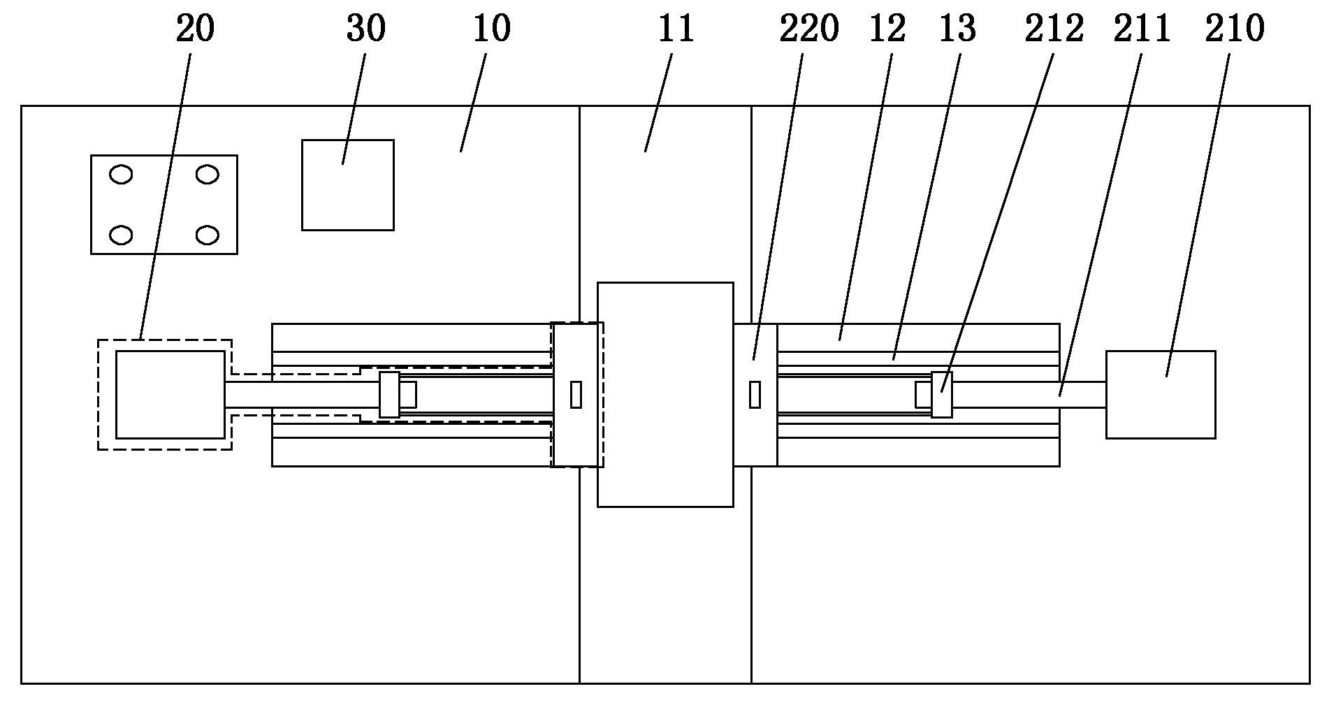
[0013] refer to figure 1 with figure 2 , the clamping device of the present invention is mainly composed of a workbench 10, a clamping mechanism 20 and a controller 30, the clamping mechanism 20 and the controller 30 are all assembled on the workbench 10, and each part is described in detail below:

[0014] The workbench 10 is mainly used to support the clamping mechanism and the controller. The middle area of ​​the workbench 10 is the workpiece positioning area. During use, the workpiece is placed in the positioning area 11, and the workpiece can be pre-positioned through the positioning area. The workbench is provided with chute 12 located on the left and right sides of the workpiece positioning area, and a chute 13 for cooperating with the rolling element device in the clamping mechanism is provided at the bottom of each chute, when the clamping mechanism When the jig is switched from the sliding mode to the rolling mode, the rolling element device will fall into the slid...


PUM


Abstract

The invention discloses a clamping device. The middle zone of a workbench is a workpiece positioning zone; the workbench is provided with chutes positioned on the left and the right of the workpiece positioning zone; the workbench is also symmetrically provided with one pair of clamping mechanisms positioned on the left and the right of the workpiece positioning zone; each clamping mechanism comprises a driving device and a fixture fixedly connected with the driving device; the fixture is in sliding fit in the chute on the workbench; a controller used for giving an action order is fixed on the workbench; and the output end of the controller is electrically connected with the driving device of the clamping mechanism. The clamping device is favorable for improving the positioning precision of a workpiece to be processed.

Description

technical field [0001] The invention relates to a tool in the technical field of machining, in particular to a clamping device for clamping a workpiece to be processed. Background technique [0002] When the workpiece is processed in industrial production, in order to ensure the accuracy of the workpiece, it is necessary to fix the workpiece with a clamping device before processing it. The existing clamping device comprises a left clamp and a right clamp, wherein one left clamp is fixed, and the right clamp can move left and right under the drive of the driving device. After the workpiece is placed on the workbench, driven by the driving device, the right fixture moves towards the direction close to the workpiece, clamps and fixes the workpiece together with the left fixture, and then processes it with the tool. Since there is a certain difference in the size of the workpiece, and the distance between the tool machining center and the left fixture is fixed, there is a certa...

Claims


Application Information

Patent Timeline
Patent Type & Authority Applications(China)
IPC IPC(8): B23Q3/06
Inventor 张顺
Owner CHANGZHOU SHENGFA BULB FACTORY
Why Eureka
Try Eureka