Full-contact 180-degree plate turnover machine

A full-contact, turning machine technology, applied in the direction of turning objects, pile separation, thin material processing, etc., can solve the problems of lack of guidance and positioning, occupying large plant space, staff injuries, etc., to reduce smashed foundations. The risk of the seat, saving the space of the workshop, and the effect of low manufacturing cost

Inactive Publication Date: 2012-03-07
SHANDONG SHUIBO WELDING & CUTTING EQUIP MFG CO LTD
View PDF3 Cites 12 Cited by
  • Summary
  • Abstract
  • Description
  • Claims
  • Application Information

AI Technical Summary

Problems solved by technology

However, it is found that there are the following deficiencies during use: 1. Because the size of the two overturning brackets of the existing overturning device determines the area that can overturn the largest plate, the floor space used by the existing overturning device should be at least the largest plate area. 2. When the existing overturning device overturns the plate, the plate as a whole is always above the base of the overturning device. Once the plate slips, the gravity of the entire plate plus the momentum of the fall is enough to move the base. If the seat and the overturning and tilting devices on it are smashed, it will also cause injury to the surrounding operators; 3, due to the two overturning brackets of the existing overturning device, the positions of the hinge shafts are fixed, and the two hinge shafts The fixed distance between the two overturning brackets must have a large angle between them, and they cannot be closed in parallel. Therefore, the plates, especially the thinner ones, lack the necessary guiding and positioning functions during the handover process of the two overturning brackets, and are prone to occur. If it falls off, it will not only cause the loss of the plate, but also cause harm to the surrounding staff

Method used


Image

  • Full-contact 180-degree plate turnover machine
  • Full-contact 180-degree plate turnover machine
  • Full-contact 180-degree plate turnover machine

Examples


Embodiment Construction

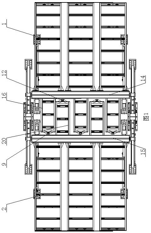
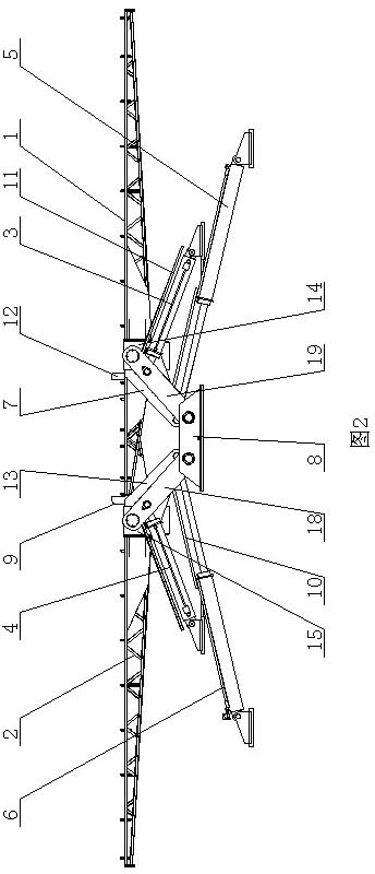
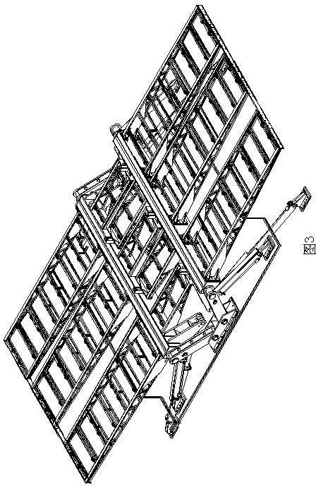
[0009] The full-contact 180-degree turning machine of the present invention includes a base 8 on which a first turning mechanism and a second turning mechanism are installed, and the first turning mechanism and the second turning mechanism are distributed left and right; the first turning mechanism is composed of The first overturning frame 1, the first connection seat 14, the first swing bar 19, the first overturning drive device and the first tilting drive device are connected to form, and the first overturning frame 1 is fixedly installed on the first connection seat 14, and the first connection seat 14 A first fork 19 is respectively installed at both ends, and the two first fork 19 are parallel, and the two ends of each first fork 19 are respectively hinged with the base 8 and the first connecting seat 14; A tilting drive device, the executive part of the first tilting drive device is hinged with the first swing rod 19, and the first swing rod 19 can be driven by the first...


PUM


Abstract

The invention discloses a full-contact 180-degree plate turnover machine which comprises a base, wherein two turnover mechanisms are arranged on the base; the first turnover mechanism is formed by connecting a first turnover stand, a first connecting seat, first swing rods, a first turnover driving device and a first inclined driving device; the first turnover stand is fixedly arranged on the first connecting seat, the two ends of the first connecting seat are respectively provided with the first swing rod, and two ends of each swing rod are respectively hinged with the base and the first connecting seat; a first inclined driving device is arranged on the base, and an executive component of the first inclined driving device is hinged with the first swing rod; a first turnover driving device is arranged on the base or the first swing rods, and the executive component of the first turnover driving device is connected with the first connecting seat; a first auxiliary turnover plate is fixedly arranged on the first connecting seat; the second turnover mechanism is formed by connecting a second turnover stand, a second connecting seat and an inclined turnover device, and the inclined overturn device is connected with the base; and the executive component of the inclined overturn device is connected with the second connecting seat.

Description

technical field [0001] The invention relates to the field of machining, in particular to a full-contact 180-degree turning machine. Background technique [0002] Existing devices that can carry out 180-degree overturning of large-area plates all turn over the plates from the overturning support on one side to the overturning support on the other side. However, it is found that there are the following deficiencies during use: 1. Because the size of the two overturning brackets of the existing overturning device determines the area that can overturn the largest plate, the floor space used by the existing overturning device should be at least the largest plate area. 2. When the existing overturning device overturns the plate, the plate as a whole is always above the base of the overturning device. Once the plate slips, the gravity of the entire plate plus the momentum of the fall is enough to move the base. If the seat and the overturning and tilting devices on it are smashed,...

Claims


Application Information

Patent Timeline
Patent Type & Authority Applications(China)
IPC IPC(8): B65H15/00
Inventor 刘宪福
Owner SHANDONG SHUIBO WELDING & CUTTING EQUIP MFG CO LTD
Why Eureka
Try Eureka