Adjustable continuous injector

A syringe and injection volume technology, applied in veterinary instruments, medical science, etc., can solve the problems of unstable movement of the core rod, gap generation, inaccurate injection volume control, etc., and achieve long service life, reasonable structure, and control stability. Good results

Active Publication Date: 2014-07-02
王喜增
View PDF6 Cites 2 Cited by
  • Summary
  • Abstract
  • Description
  • Claims
  • Application Information

AI Technical Summary

Problems solved by technology

Since the upper end of the movable handle is connected and fixed with the core rod through the connecting block and the fixed pin, if it is gripped continuously and quickly for a long time, there will be friction between the movable handle, the connecting block and the core rod, and a gap will be generated, resulting in unstable movement of the core rod and control of the injection volume. Inaccurate

Method used


Image

  • Adjustable continuous injector
  • Adjustable continuous injector
  • Adjustable continuous injector

Examples


Embodiment Construction

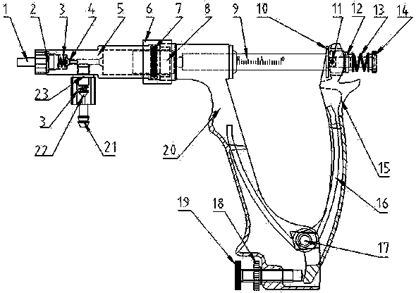
[0015] From figure 1 It can be seen from the figure that an adjustable continuous syringe includes a sleeve 5, a piston 8, a core rod 9, a fixed handle 20, a movable handle 15, an adjusting screw 19, and the like. The piston 8 is installed on the front end of the core rod 9, driven by the core rod 9 to move in the sleeve 5, the front end of the sleeve 5 is provided with a needle seat 1, and a gasket 2, a spring 3, Check valve 4. The cavity of the sleeve 5 is also connected to a connector 21 through a connecting nut 23, and a one-way suction valve 22 and a spring 3 are housed in the connector 21 for connecting an infusion hose or an infusion bottle. The above composition structure is basically the same as that of the prior art and will not be described in detail.

[0016] The rear part of the sleeve 5 of the present invention is connected and fixed to the handle 20 through the connecting sleeve 6 and the sealing ring 7 . The piston 8 cooperates with the sealing ring 7 for se...


PUM


Abstract

The invention relates to an adjustable continuous injector. The injector comprises a sleeve, a piston, a core rod, a fixed handle, a movable handle and an adjusting screw rod, wherein the rear part of the sleeve is connected with the fixed handle; a screw hole is formed at the bottom of the fixed handle; the adjusting screw rod passes through the screw hole and is contacted with the lower lateral face of the movable handle; the adjusting screw rod pushes the movable handle to rotate with a pin roll, and the core rod is driven to displace, so that adjustment of injection amount is realized; a slotted hole is formed in the middle of the upper end of the movable handle along the axial direction of the core rod; the movable handle is sleeved on the core rod; a core rod catch, a gasket and a spring are sleeved on the core rod close to protruded cambered surfaces of the front and rear parts of the movable handle; and when the movable handle drives the core rod to move front and back, the movable handle can freely and slightly float up and down relative to the core rod, the core rod is prevented from generating friction, and axial movement of the core rod is not influenced. The adjustable continuous injector has the advantages of reasonable structure, accurate quantitation, convenience in adjustment, reliability in operation, good stability of injection quantity control and long service life.

Description

technical field [0001] The invention relates to a veterinary medical device, in particular to an adjustable continuous syringe. Background technique [0002] We know that at present, the veterinary continuous syringes on the market mainly include a sleeve, a piston, and a core rod. The piston is installed at the front end of the core rod and is driven by the core rod to move back and forth in the sleeve. The communicating infusion channel is provided with a needle seat at the front end of the sleeve. The injection mechanism of a continuous syringe is mostly a piston-type push mechanism with a handle connecting rod. The continuous injection can be realized by holding the handle. When entering the liquid medicine, a joint is connected to a rubber hose at the continuous feeding part, and the other end of the rubber hose is connected to a long needle. Insert into the original liquid medicine bottle, or use the spare liquid storage bottle, pour the medicine of the original medic...

Claims


Application Information

Patent Timeline
Patent Type & Authority Patents(China)
IPC IPC(8): A61D7/00
Inventor 王喜增
Owner 王喜增
Why Eureka
Try Eureka