
Torque measuring mechanism for spanner

A torque measurement and wrench technology, applied in the direction of wrenches, screwdrivers, manufacturing tools, etc., can solve the problems of fuzzy single digits, cumbersome operation and inconvenience.

Active Publication Date: 2013-09-18
MATATAKITOYO TOOL
View PDF5 Cites 1 Cited by
  • Summary
  • Abstract
  • Description
  • Claims
  • Application Information

AI Technical Summary

Problems solved by technology

[0005] 1. The torque measurement of these patent cases relies on the way the handle is rotated relative to the pipe, and the scale on the surface of the tool is aligned with the edge of the handle by visual inspection. It is easy to cause some errors in the measured value due to the angle.
[0006] 2. The aforementioned measurement values ​​are accurate to hundreds or tens of digits, but the single digits are rather vague
[0007] 3. In the U.S. Patent No. 7,631,583, each plate must be turned to adjust the torque value of the wrench. The operation is quite cumbersome, and it is very inconvenient for the user.

Method used


Image

  • Torque measuring mechanism for spanner
  • Torque measuring mechanism for spanner
  • Torque measuring mechanism for spanner

Examples


Embodiment Construction

[0055] In order to further explain the technical solution of the present invention, the present invention will be described in detail below through specific examples.

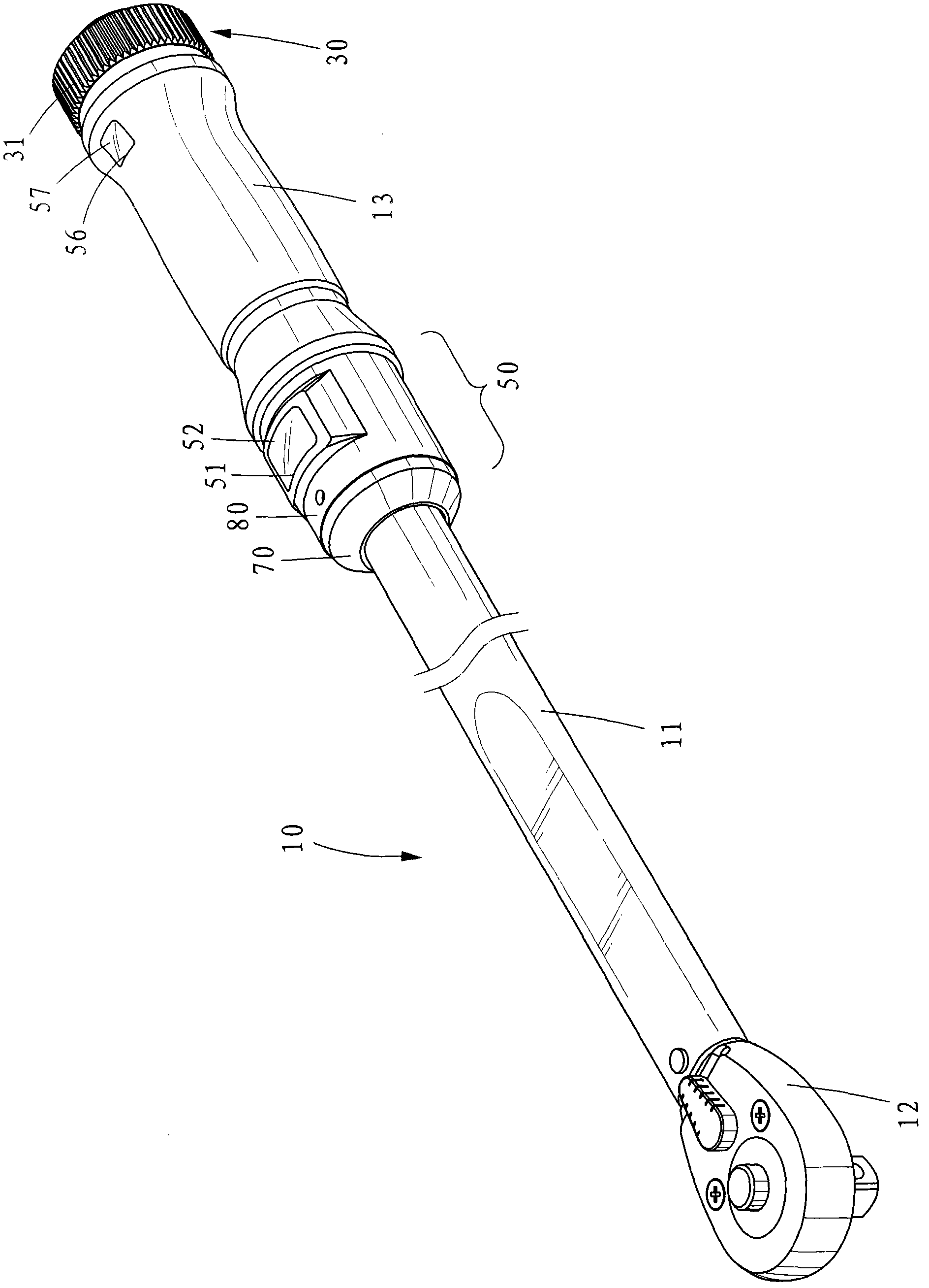
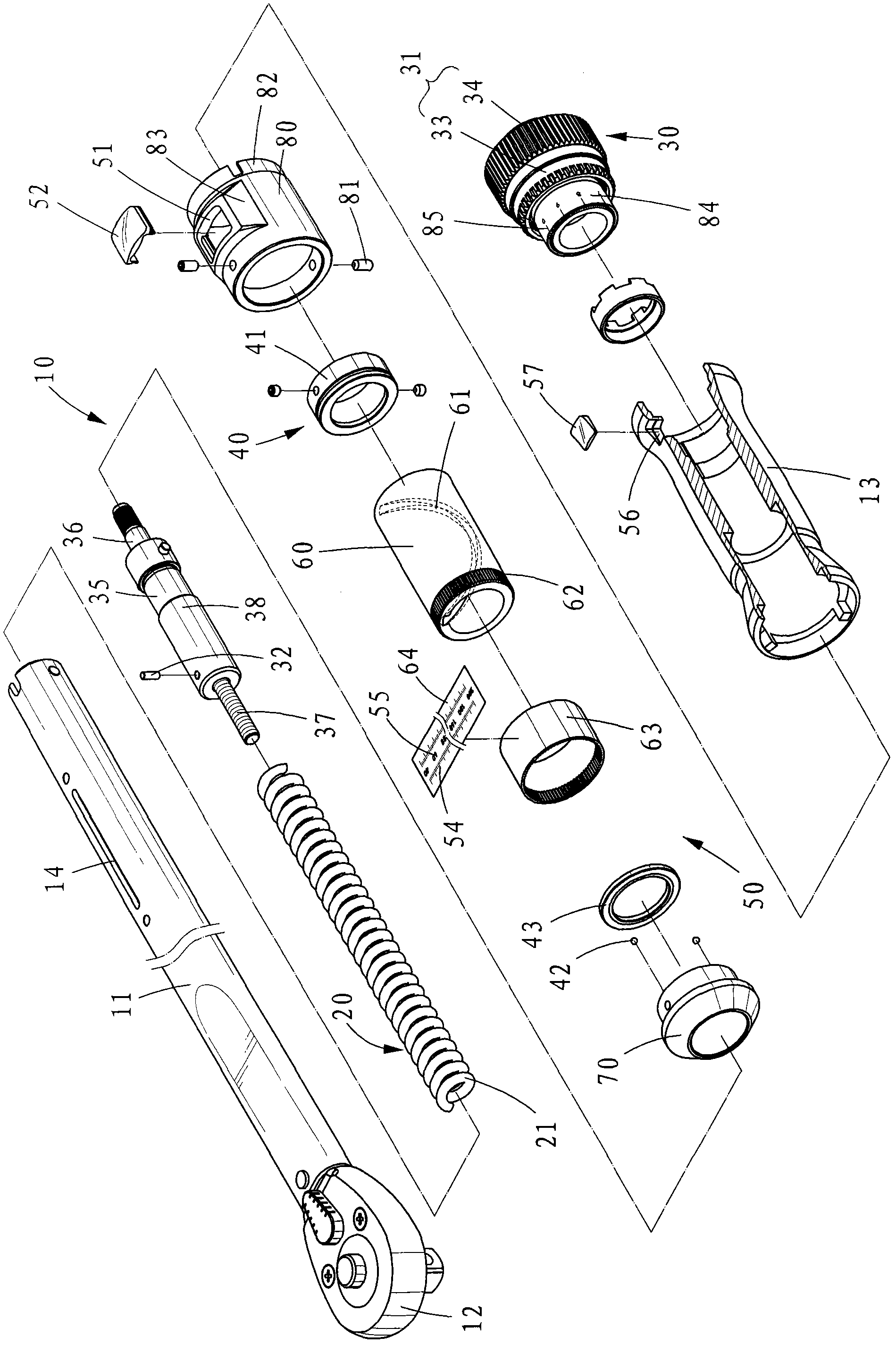
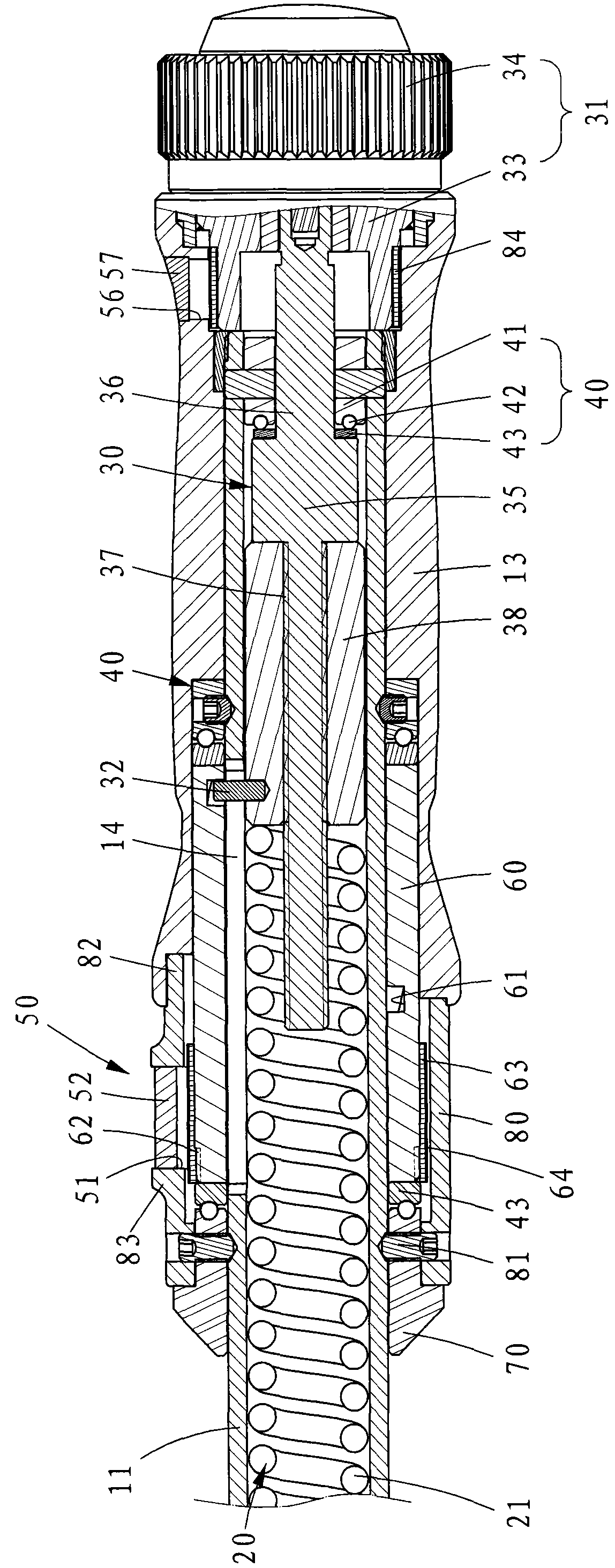
[0056] see Figure 1 to Figure 3 , its disclosed wrench 10 is connected with a head 12 at one end of the pipe fitting 11, and the other end of the pipe fitting 11 is connected with a handle 13, and is provided with an elongated hole 14 on the pipe body. Using the head 12 of the wrench 10 as a fulcrum, an external force is applied to the handle 13, and the swing pipe 11 reciprocates, that is, the torque can be transmitted to the workpiece through the head 12.

[0057] Wherein, the pipe 11 is connected with the head 12 through the torque output structure 20 . The torque output structure 20 includes a spring 21 embedded in the pipe fitting 11. For other structures, please refer to US Patent No. 4,870,879, which is not the focus of this case, so it will not be described in detail.

[0058] A torque adjusting devi...


PUM


Abstract

The invention discloses a torque measuring mechanism for a spanner. The torque measuring mechanism at least comprises a measuring barrel, a fixed ring and a sleeve, wherein a spiral track is sunken into the barrel, the measuring barrel can be stressed to automatically rotate, and the exterior of the barrel displays a plurality of scales; the fixed ring is used for limiting the measuring barrel to automatically rotate without displacement; and the sleeve is limited at the outer part of the measuring barrel and provided with a window facing the scale part. The torque measuring mechanism can assist a user in easily identifying the torque value of the adjusted spanner.

Description

technical field [0001] The invention relates to the field of torque measurement, in particular to a measuring mechanism suitable for a ratchet wrench. Background technique [0002] The existing ratchet wrench, like the wrench disclosed in U.S. Patent No. 4,870,879, connects one end to the end of a pipe through a torque output structure, and the other end of the pipe is connected to a handle, and a handle is installed between the pipe and the handle. Torque adjustment device. [0003] This torque adjustment device consists of an adjustment knob assembled on the handle. Several scales are displayed on the edge of the adjustment knob adjacent to the handle. These scales are separated from each other by an appropriate distance and can only measure the metric unit N-m (Newton-meter) and the imperial unit lb-ft. (pound-feet) or the approximate value of the Taiwanese unit kg-m (kg-meter), but cannot measure the precise torque value. [0004] Similar torque measurement technologie...

Claims


Application Information

Patent Timeline
Patent Type & Authority Patents(China)
IPC IPC(8): B25B23/142
Inventor 吴日淳吴逸民
Owner MATATAKITOYO TOOL
Learn More