Electrically-driven speed change device for vehicles

A speed change device and electric drive technology, which is applied in the direction of transmission device, gear transmission device, differential transmission device, etc., can solve the problems of complex structure and increased cost

Inactive Publication Date: 2012-03-14
SHANGHAI E PROPULSION AUTO TECH
View PDF5 Cites 34 Cited by
  • Summary
  • Abstract
  • Description
  • Claims
  • Application Information

AI Technical Summary

Problems solved by technology

It can be seen that although the electric drive device realizes the two-speed drive of the electric vehicle, the structure is relatively complicated, and at least two clutches (overrunning clutch 4 and ordinary clutch 12) are used, which increases the cost.

Method used


Image

  • Electrically-driven speed change device for vehicles
  • Electrically-driven speed change device for vehicles
  • Electrically-driven speed change device for vehicles

Examples


no. 1 approach

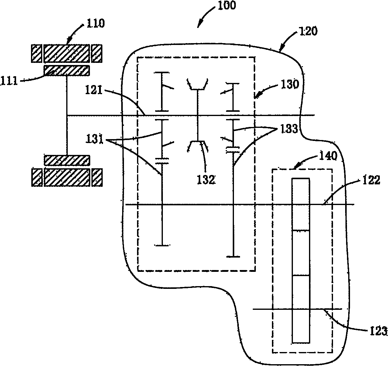
[0031] figure 2 A schematic diagram of a first embodiment of the electric drive transmission device for a vehicle according to the present invention is shown. exist figure 2 Among them, the electrically driven transmission device for a vehicle according to the present first embodiment is generally indicated by reference numeral 100 . As can be seen from the figure, the electric drive transmission device 100 for a vehicle according to the first embodiment includes a motor 110 and a transmission mechanism 120 . The motor 110 is indicated by hatching, the stator of the motor 110 is formed on the periphery thereof, and the rotor 111 of the motor 110 is formed on the inner periphery thereof. Transmission mechanism 120 is shown in the curve frame (this curve itself does not belong to the part of device of the present invention), and it comprises input shaft 121, speed change mechanism 130, intermediate shaft 122, reduction mechanism 140 and output shaft 123, and motor 110 compri...

no. 2 approach

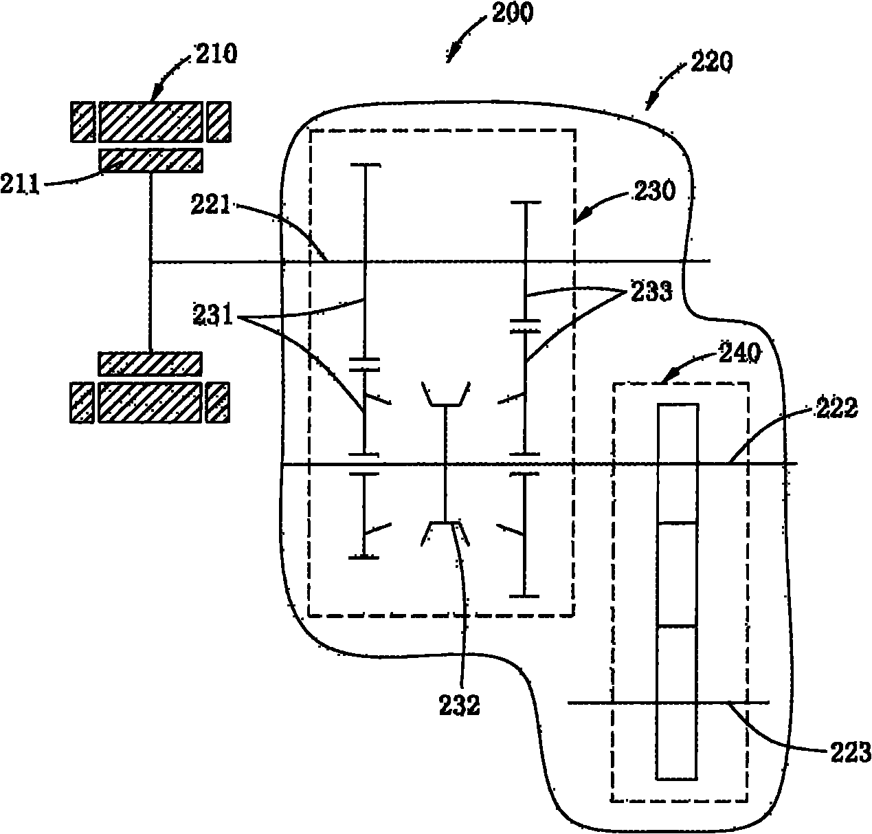
[0035] image 3 A schematic diagram of a second embodiment of the electric drive transmission device for a vehicle according to the present invention is shown. exist image 3 Among them, the electrically driven transmission device for a vehicle according to the present second embodiment is generally indicated by reference numeral 200 . It can be seen from the figure that the electric drive transmission device 200 for a vehicle according to the second embodiment includes a motor 210 and a transmission mechanism 220 . The motor 210 is indicated by hatching, the stator of the motor 210 is formed on the periphery thereof, and the rotor 211 of the motor 210 is formed on the inner periphery thereof. Transmission mechanism 220 is shown in the curve frame (this curve itself does not belong to the part of device of the present invention), and it comprises input shaft 221, speed change mechanism 230, intermediate shaft 222, reduction mechanism 240 and output shaft 223, and motor 210 c...

no. 3 approach

[0039] Figure 4 A schematic diagram of a third embodiment of the electric drive transmission device for a vehicle according to the present invention is shown. exist Figure 4 Among them, the electrically driven transmission device for a vehicle according to the present third embodiment is generally indicated by reference numeral 300 . As can be seen from the figure, the electric drive transmission device 300 for a vehicle according to the third embodiment includes a motor 310 and a transmission mechanism 320 . The motor 310 is indicated by hatching, the stator of the motor 310 is formed on the periphery thereof, and the rotor 311 of the motor 310 is formed on the inner periphery thereof. The transmission mechanism 320 is shown in the curve frame (this curve itself does not belong to a part of the device of the present invention), and it includes an input shaft 321, a speed change mechanism 330, an intermediate shaft 322, a reduction mechanism 340 and an output shaft 323, an...


PUM


Abstract

The invention provides an electrically-driven speed change device for vehicles. The electrically-driven speed change device comprises a motor and a transmission mechanism, wherein the transmission mechanism comprises an input shaft, a speed change mechanism, an intermediate shaft, a retarding mechanism and an output shaft; the motor comprises a stator and a rotor; the rotor is connected with the input shaft; the input shaft is connected to the intermediate shaft by the speed change mechanism; the intermediate shaft is connected to the output shaft by the reducing mechanism; the speed change mechanism comprises a parallel shaft gear set and a synchronizer, and realizes gear shifting by the synchronizer. By the electrically-driven speed change device for the vehicles, a clutch is saved, namely the gear shifting can be realized conveniently by the synchronizer, and two-gear transmission and multi-gear transmission are easy to realize; and reverse gear can be realized conveniently by controlling the motor appropriately, so an idle pulley for realizing transmission reversing in common vehicles is saved, the cost is saved effectively, and a structure is simplified.

Description

【Technical field】 [0001] The invention relates to an electric drive transmission device; more specifically, the invention relates to an electric drive transmission device for a vehicle. 【Background technique】 [0002] Speed ​​change devices are widely used in equipment for speed and traction transmission of machines such as automobiles. Common speed change devices include various modes such as gear transmission, belt transmission, and chain transmission, which usually have a driving shaft and a driven shaft for transmission, or an input shaft and an output shaft for transmission. In the field of vehicles, the speed change device is usually a gear transmission device that can change the transmission ratio of the output shaft and the input shaft in steps, also known as a speed changer or a gearbox. The gear transmission is usually a multi-shaft ordinary gear transmission, and some use planetary gear transmission. Ordinary gear transmission transmission mechanisms are general...

Claims


Application Information

Patent Timeline
Patent Type & Authority Applications(China)
IPC IPC(8): B60K17/12B60K17/16F16H3/12F16H48/00
Inventor 朱军葛海龙
Owner SHANGHAI E PROPULSION AUTO TECH
Why Eureka
Try Eureka