Front structure for a motor vehicle

A body and automobile technology, applied in vehicle components, vehicle safety arrangements, superstructure sub-assemblies, etc., can solve the problem of not being able to ensure the accurate orientation of the bumper for a long time.

Inactive Publication Date: 2012-03-14
GM GLOBAL TECH OPERATIONS LLC
View PDF7 Cites 4 Cited by
  • Summary
  • Abstract
  • Description
  • Claims
  • Application Information

AI Technical Summary

Problems solved by technology

[0003] A disadvantage in such a front end is that the exact orient...

Method used


Image

  • Front structure for a motor vehicle
  • Front structure for a motor vehicle
  • Front structure for a motor vehicle

Examples


Embodiment Construction

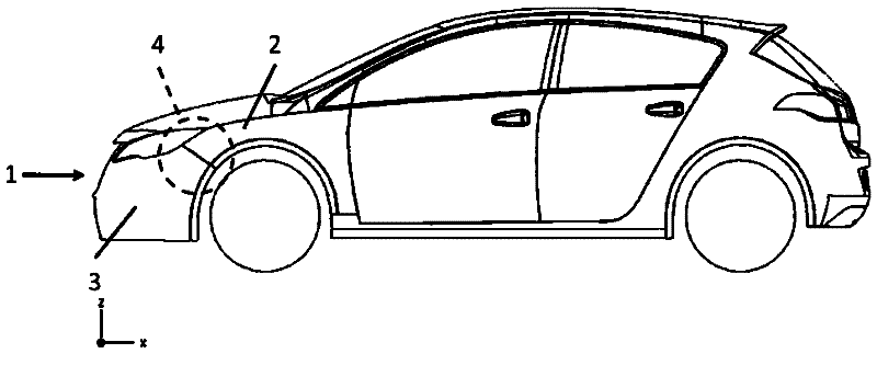
[0023] figure 1 A motor vehicle with a front end 1 is shown. The front body 1 has a fender 2 and a bumper 3 delimiting the front end 1 in the direction of travel. The bumper 3 is connected to the fender 2 via fastening means 4 . exist figure 1 , the fixing device 4 is covered by the fender 2 and the bumper 3 .

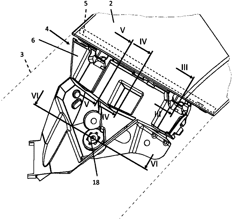
[0024] figure 2 show figure 1 Part of the front end 1 of the center body with the fender 2 and the fastening means 4 . In order to simplify the illustration, the outline of the bumper 3 is shown with dashed lines. The fastening device 4 has a fastening flange 5 fastened to the fender 2 and a guide rail 6 connected to the fastening flange 5 . Guide rail 6 is arranged below bumper 3, and in figure 2 The middle fixed edge plate 5 is mostly blocked by the fender 2 .

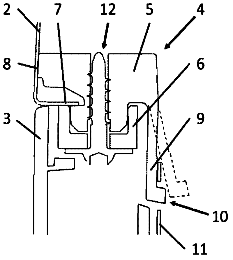
[0025] image 3 Shows sectioning along section line III-III figure 2 An enlarged cross-sectional view of the fixation device 4 in . It can be seen here that the fastening flange 5 bears against...


PUM


Abstract

A front structure 1 for a motor vehicle has holding means 4 for connecting a bumper 3 to a wing or fender 2 comprising a fastening strip 5 and a guide rail 6. The fastening strip 5 spring-elastically supports itself on the wing or fender 2 and is screwed to the guide rail 6. The bumper 3 is latched to the guide rail 6. Because of this an even joined course between the bumper 3 and the wing or fender 2 can be ensured.

Description

technical field [0001] The invention relates to a front body for a motor vehicle with a bumper pointing in the direction of travel, a fender adjoining the bumper and fastening means for fastening the bumper to the fender. Background technique [0002] Such a front end is known, for example, from DE 44 32 766 A1. In such a front end, the fastening means has a clamping body which connects the mutually opposite flanges of the fender and the bumper to one another. The bumper also has snap-in hooks for the web of the snap-back clamping body. [0003] A disadvantage of such a front end is that the exact orientation of the bumper relative to the fender cannot be permanently ensured. For example, the clamping body changes position during assembly relative to the fender, so that the position of the bumper relative to the fender is automatically changed. The change in the position of the bumper relative to the fenders affects the appearance of the front end of the body. Contents ...

Claims


Application Information

Patent Timeline
IPC IPC(8): B60R19/24B62D25/16B62D25/08
CPCB60R19/24B60R2019/247
Inventor M.L.萨克斯T.霍克R.厄沃特
Owner GM GLOBAL TECH OPERATIONS LLC
Why Eureka
Try Eureka