Automatic drainage valve of pedestal pan and working method thereof

A technology of automatic drainage and working methods, which is applied in water supply devices, flushing equipment with water tanks, buildings, etc., can solve problems such as forgetting to flush, not flushing, and unstable induction, etc., to prolong power supply time, save electric energy, and reduce power consumption. Electrode small effect

Inactive Publication Date: 2012-03-14
陆建钢
View PDF6 Cites 13 Cited by
  • Summary
  • Abstract
  • Description
  • Claims
  • Application Information

AI Technical Summary

Problems solved by technology

But because the infrared rays cannot be blocked, the sensing window of the sensor is higher than the height after the toilet cover is lifted upwards, so it is not convenient to clean the toilet, and affects the appearance of the toilet, and it is not suitable for wearing clothes of different colors in actual use. For people, the induction is not very stable, and the phenomenon of not flushing will also occur.
2. There is also an automatic toilet drain valve, which has improved the above defects: that is, the controller and the electric drain valve are separated and connected wirelessly. The controller has a toilet cover mounting surface, that is, the toilet automatic drain valve is installed on the seat When it is on the toilet, the controller is installed on the inner surface of the toilet cover. When it is lifted upwards, infrared rays can detect people. The controller is powered by batteries, which shortens the sensing distance with the toilet user and makes the sensing and work more reliable. There is no obtrusive thing on the water tank cover; but this technical solution brings new problems, that is, the sensor window is easily stained by water and urine, which affects the sensing of the human body and is not convenient for cleaning the toilet cover and affects the appearance of the cover
Although this s

Method used


Image

  • Automatic drainage valve of pedestal pan and working method thereof
  • Automatic drainage valve of pedestal pan and working method thereof
  • Automatic drainage valve of pedestal pan and working method thereof

Examples


Example Embodiment

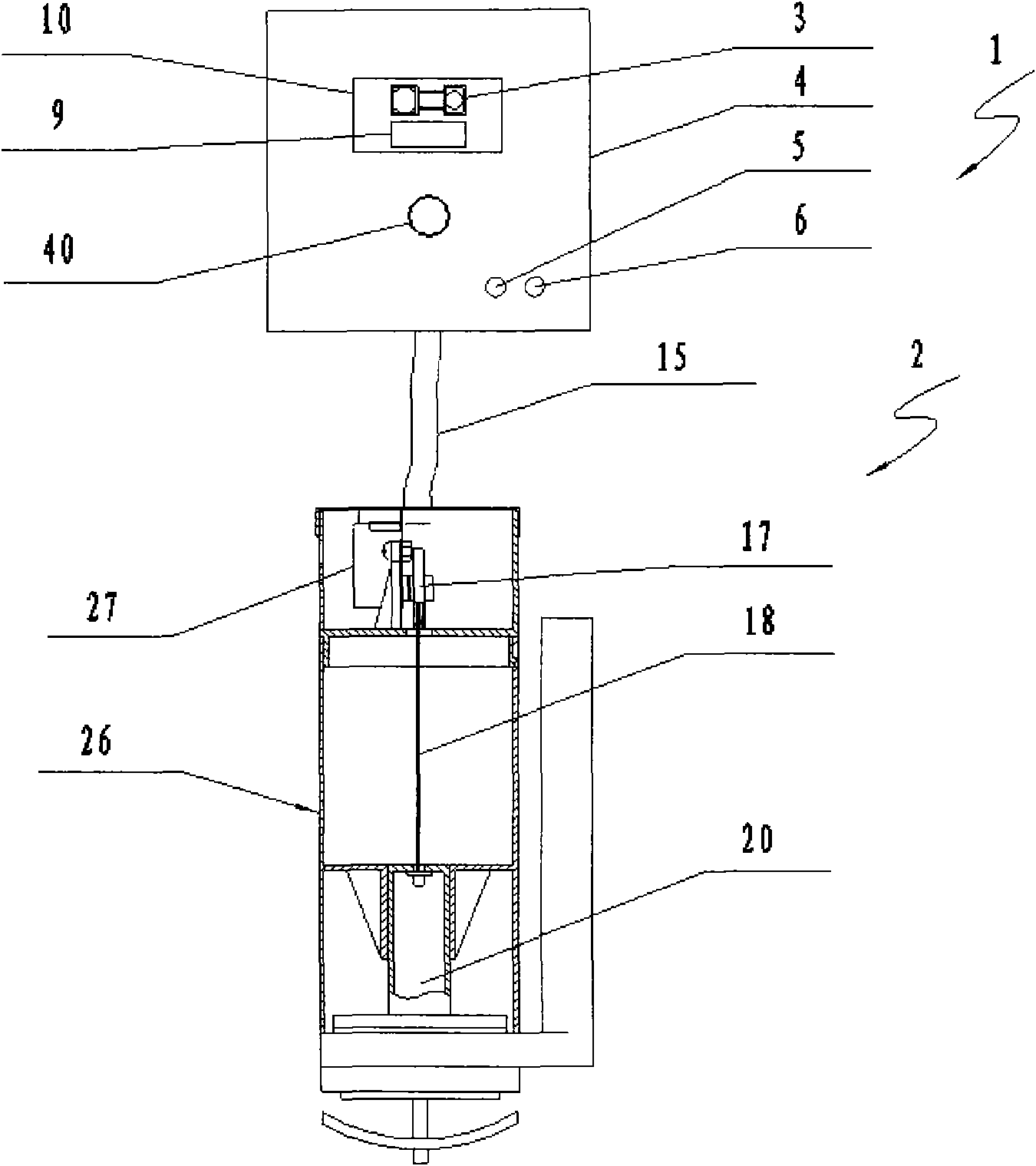
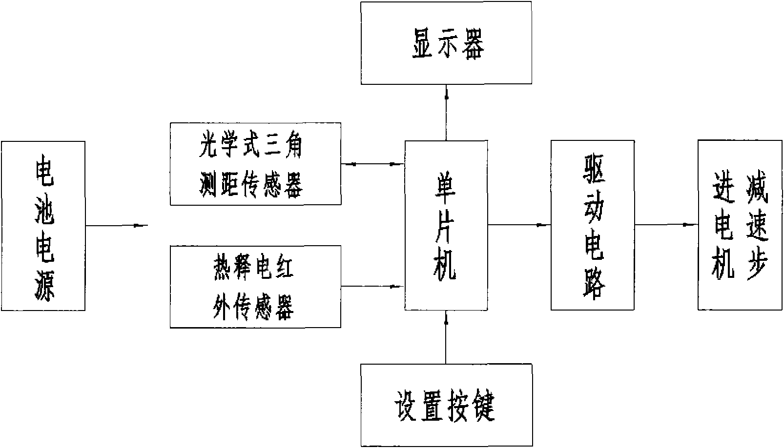
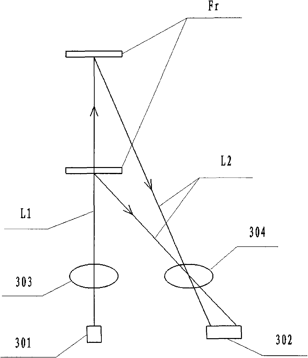
[0036] Example one, as Figure 1 to Figure 5 As shown, the controller 1 of the toilet automatic drain valve of this embodiment includes: an optical triangulation sensor 3, a pyroelectric infrared sensor 40, an output signal receiving the optical triangulation sensor, and a pyroelectric infrared sensor. A single-chip microcomputer for outputting and processing signals, a driving circuit controlled by the single-chip microcomputer, setting buttons 5 and 6 for setting values ​​and functions, a display circuit 9 for displaying the setting content, a battery power supply, and a controller housing 4 with a wall fixed end, The controller shell is a surface-mounted structure that does not damage the wall. Among them, the optical triangulation ranging sensor includes: a light-emitting element that emits irradiation light, a light-emitting lens that focuses the irradiation light and irradiates the distance-measuring object, a light-receiving lens that collects the reflected light reflec...

Example Embodiment

[0050] Example two, as Figure 6 to Figure 11 As shown, the controller 1 of the toilet automatic drain valve of this embodiment includes: an optical triangulation sensor 3, a pyroelectric infrared sensor 40, an output signal receiving the optical triangulation sensor, and a pyroelectric infrared sensor. A single-chip microcomputer for outputting and processing signals, a wireless transmission circuit I for transmitting the instructions of the single-chip microcomputer, setting buttons 5 and 6 for setting values ​​and functions, a display circuit for displaying setting contents, a controller housing 4 with a wall fixed end and providing control The battery power supply of the device power. The electric drain valve 2 includes: a wireless transmission circuit II for transmitting instructions of the single-chip microcomputer, a single-chip microcomputer II for receiving instructions from the single-chip microcomputer, a drive circuit driven by the single-chip microcomputer II, an ...


PUM


Abstract

The invention discloses an automatic drainage valve of a pedestal pan and a working method thereof. The automatic drainage valve of the pedestal pan consists of a controller and an electric drainage valve, and comprises an optical triangular ranging sensor, a pyroelectric infrared sensor, a single chip for receiving and processing the output signals of the optical triangular ranging sensor and pyroelectric infrared sensor, a driving circuit controlled by the single chip, an electric device driven by the driving circuit, a water stop valve cover controlled by the electric device, a controller shell arranged at the fixed end of the wall and an electric water drainage valve body provided with a pedestal pan water tank fixing mechanism. Through the invention, the stable and reliable water flushing of the automatic drainage valve of the pedestal pan is realized, and the automatic drainage valve is powered by a battery. In the working method of the automatic drainage valve of the pedestal pan, the optical triangular ranging sensor does not work at ordinary times but works intermittently when someone uses the pedestal pan, thereby greatly reducing the power consumption and prolonging the service time and life of the battery.

Description

technical field [0001] The invention relates to a toilet drain valve, in particular to an automatic toilet drain valve and a working method thereof. Background technique [0002] The toilet automatic drain valve is installed on the ordinary toilet, which can make the ordinary toilet become an automatic flush toilet; The toilet is divided into two levels of flushing, large and small, to save water resources. [0003] The toilet automatic drain valve is composed of a controller and an electric drain valve. The existing toilet automatic drain valve generally has the following forms: 1. The controller and the drain valve are integrated or connected up and down, and are installed on the toilet. At this time, the sensor in the controller protrudes from the perforation in the middle of the toilet water tank cover or is placed on the water tank cover. The infrared emission tube in the sensor emits infrared signals, and the infrared signals are reflected back after being blocked by ...

Claims


Application Information

Patent Timeline
IPC IPC(8): E03D1/34E03D5/10
Inventor 陆建钢
Owner 陆建钢
Why Eureka
Try Eureka