Injection jet engine

A jet engine and power technology, applied in the direction of ramjet engine, combined engine, machine/engine, etc., can solve the problems of engine use, complex structure, fast running speed, etc.

Inactive Publication Date: 2012-03-14
靳北彪
View PDF4 Cites 19 Cited by
  • Summary
  • Abstract
  • Description
  • Claims
  • Application Information

AI Technical Summary

Problems solved by technology

[0002] In order to generate propulsion, there are engines that generate propulsion through fans, engines that use rocket jet channels to generate propulsion, and turbojet engines, turbofan jet engines, and ramjet engines. However, these engines either have complex structures or require special operating speeds. fast, which can be difficult to use in some situations, especially as these engines are difficult to use as engines that output rotational power

Method used


Image

  • Injection jet engine
  • Injection jet engine
  • Injection jet engine

Examples


Embodiment 1

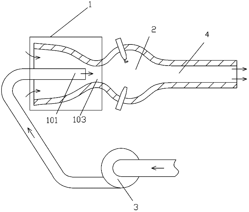
[0095] Such as figure 1 The jet jet engine shown includes a jet pump 1, a combustion chamber 2 and a high-pressure pump 3, the jet pump outlet 103 of the jet pump 1 communicates with the combustion chamber 2, and the gas working medium outlet of the combustion chamber 2 communicates with the combustion chamber 2. The injection channel 4 communicates, and the fluid outlet of the high-pressure pump 3 communicates with the motive fluid nozzle 101 of the jet pump 1 . The power fluid pressurized by the high-pressure pump 3 is ejected by the jet pump 1 and then reacts with the fuel in the combustion chamber 2 to form a high-temperature and high-pressure working fluid. The ejection channel 4 ejects to obtain propulsion.

[0096] In order to make the ejection jet engine work more efficiently and environmentally friendly, adjust the pressure of the gas working medium that is about to start working to more than 15MPa, and adjust the temperature of the gas working medium that is about ...

Embodiment 2

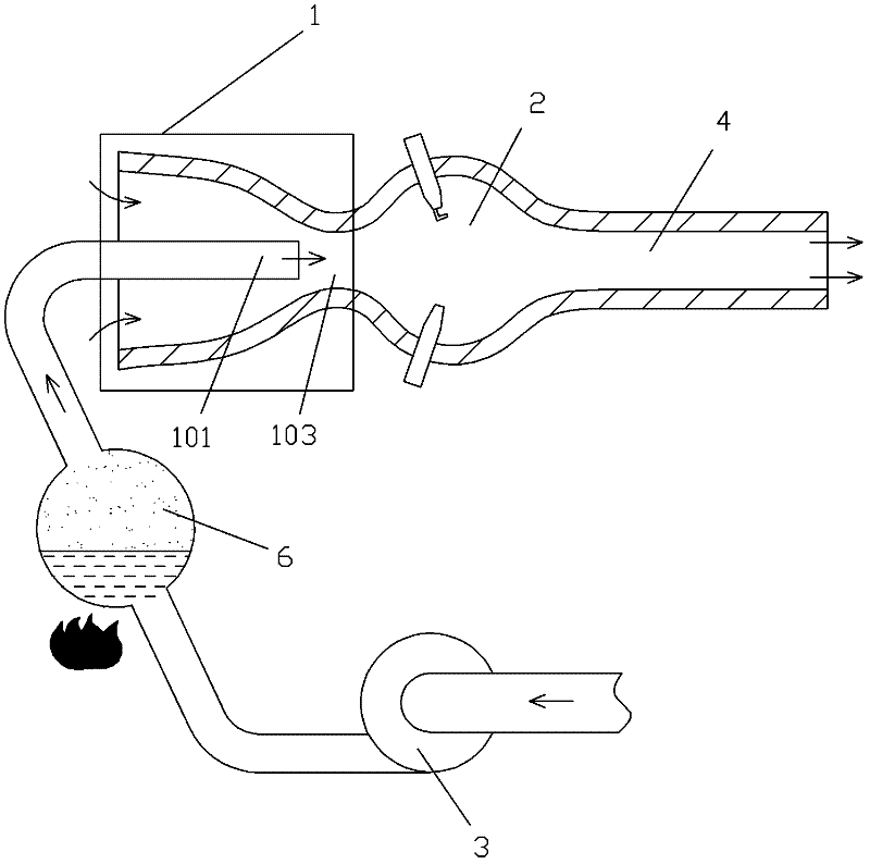
[0098] Such as figure 2 The difference between the shown ejection jet engine and Embodiment 1 is that a carburetor 6 is provided between the high-pressure pump 3 and the motive fluid nozzle 101 . The liquid working medium in the vaporizer 6 is a gas liquefaction. The working process of this scheme is: first use the high-pressure pump 3 to pressurize the liquid in the vaporizer 6, then heat the vaporizer 6 to vaporize the liquid therein into high-pressure steam, and the high-pressure steam enters the jet pump as a motive fluid to work. That is, this solution provides another method for generating high-pressure motive fluid.

Embodiment 3

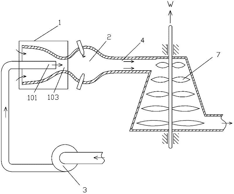
[0100] Such as image 3 The difference between the shown ejection jet engine and Embodiment 1 is that a power turbine 7 is provided at the injection port of the injection channel 4 .

[0101] During specific implementation, a power turbine 7 may also be provided in the injection channel 4 .


PUM


Abstract

The invention discloses an injection jet engine comprising a jet pump, a combustion chamber and a high-pressure pump; an exit of the jet pump is communicated with the combustion chamber; a gas medium exit of the combustion chamber is communicated with a jet channel; and a fluid exit of the high-pressure pump is communicated with a power fluid nozzle of the jet pump. Through the adoption of the injection jet engine, the efficiency of the traditional engine is greatly improved.

Description

technical field [0001] The invention relates to the field of jet propulsion, in particular to an ejector jet engine. Background technique [0002] In order to generate propulsion, there are engines that generate propulsion through fans, engines that use rocket jet channels to generate propulsion, and turbojet engines, turbofan jet engines, and ramjet engines. However, these engines either have complex structures or require special operating speeds. Fast, which is difficult to use in some cases, especially these engines are difficult to use as engines that output rotational power. For this reason, it is necessary to invent an engine that has a simpler structure and can obtain high-efficiency propulsion when running at low speeds, especially when rotating at low speeds. This type of engine can be used as an engine that outputs rotational power. Contents of the invention [0003] In order to achieve the above object, the technical scheme proposed by the present invention is ...

Claims


Application Information

Patent Timeline
Patent Type & Authority Applications(China)
IPC IPC(8): F02K7/12F02K7/16F02K1/28
Inventor 靳北彪
Owner 靳北彪
Why Eureka
Try Eureka