
Quick joint

A fast, on-body technology, applied in the direction of mechanical equipment, couplings, etc., can solve problems such as pipe swinging, injury to operators, and connection

Inactive Publication Date: 2012-03-14
刘秀雄
View PDF9 Cites 2 Cited by
  • Summary
  • Abstract
  • Description
  • Claims
  • Application Information

AI Technical Summary

Problems solved by technology

[0003] However, although the existing quick connector 70 can provide the effect of a quick connection pipeline, the existing quick connector 70 not only must make the body 71 and the positioning seat 72 respectively during manufacture, which will relatively increase the required manufacturing time. Cost and time, and the body 71 and the positioning seat 72 must be screwed together during assembly, which is quite inconvenient. In addition, the screwed joint between the body 71 and the positioning seat 72 of the existing quick connector 70 is difficult to use for a long time. In the end, it is easy to cause gas leakage, not only the connection of the pipeline cannot be accurately carried out, but also there will be hidden dangers;
[0004] Furthermore, although the existing quick joint 70 can be combined with a male joint (not shown) by sliding the positioning beads 722, so as to carry out gas transmission and use, but after use, it is desired to connect the male joint with When the existing quick connector 70 is separated, it is necessary to push the outer shell 74 by hand, so that each positioning bead 722 is separated from the male connector to release the buckle state, and then the male connector can be ejected from the existing quick connector 70 , but in the process of popping up, since the valve seat 73 is still in a ventilated state, the momentum of the high-pressure gas will accelerate the separation of the two. At this time, if the pipe connected to the male joint is not firmly grasped, the The pipe may be thrown around due to the momentum of the high-pressure gas, which may injure the operator. Therefore, when the existing quick connector 70 is separated from the male connector, it will be affected by the gas and have an instant opening and flushing. The defects not only cause inconvenience to the work, but also hidden dangers, there is something to be improved

Method used


Image

  • Quick joint
  • Quick joint
  • Quick joint

Examples


Embodiment Construction

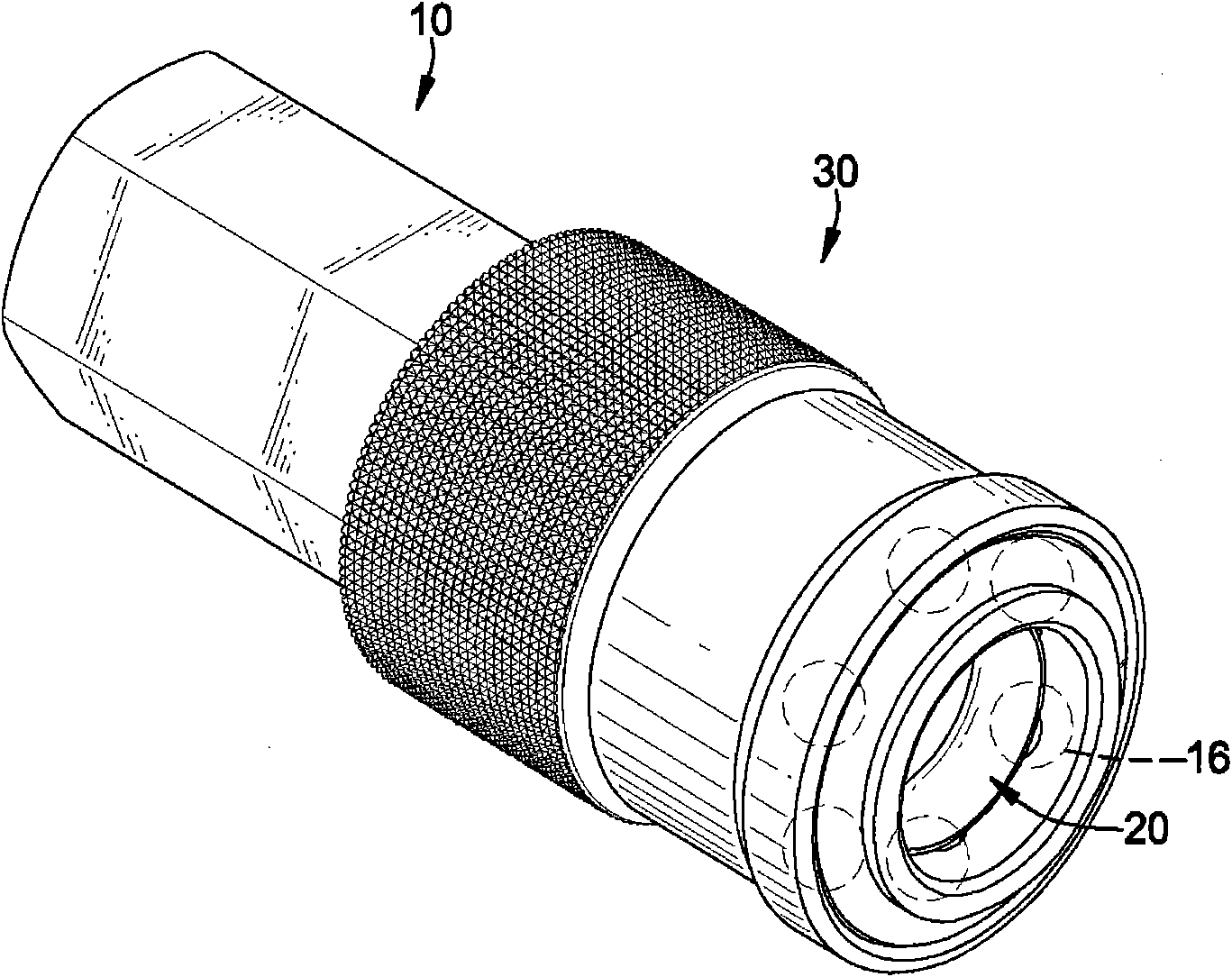
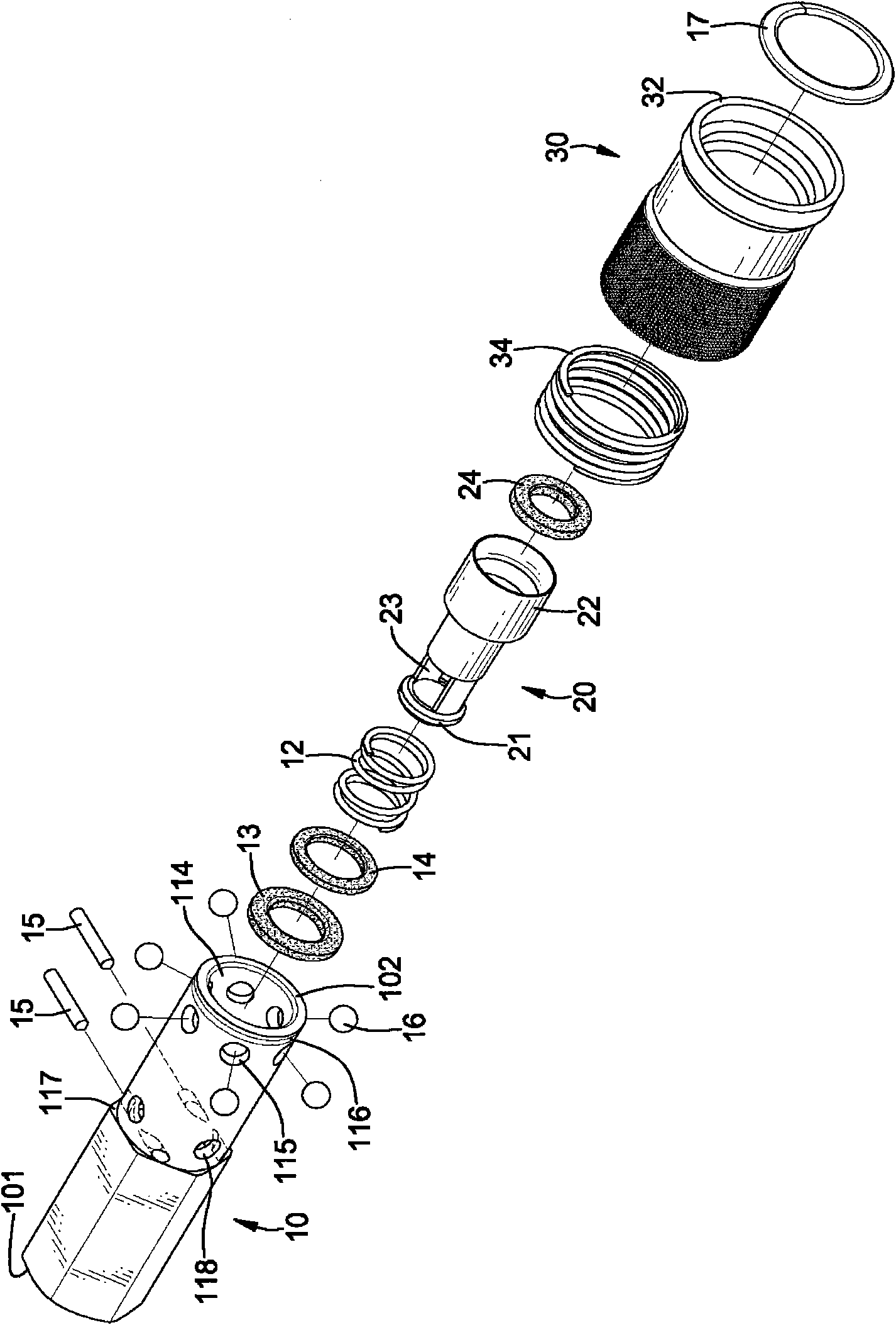
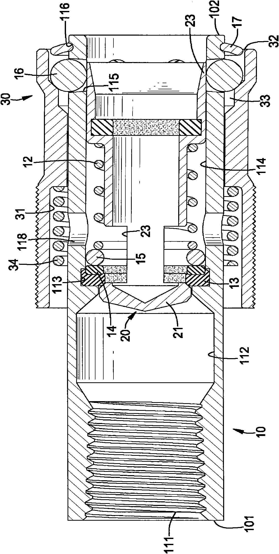
[0052] In order to understand the technical features and practical effects of the present invention in detail, and to implement them according to the contents of the description, the preferred embodiment shown in the drawings is further detailed as follows, please refer to the following Figures 1 to 4 As shown, the quick connector (Japanese standard) of the present invention is provided with a body 10, a valve seat 20 and an outer casing 30, wherein:

[0053] The body 10 is an integrally formed hollow cylinder and is provided with a joint end 101 and a positioning end 102, wherein the joint end 101 of the body 10 is used to combine with an air compressor (not shown), as image 3 or Figure 8AAs shown, the body 10 is provided with a screw thread 111 on the inner surface or the outer surface near the coupling end 101, and the body 10 is provided with an air inlet chamber 112 connected with the air compressor, an inner diameter A locking groove 113 smaller than the air inlet ch...


PUM


Abstract

The invention discloses a quick joint, which is provided with a body, a valve seat and a shell, wherein the body is provided with a bonding end, a positioning end, an air inlet chamber, a clamping groove and an air outlet chamber; the body is provided with a return spring in the air outlet chamber; a plurality of air leakage holes which are communicated with the air outlet chamber run through the middle section of the body in the radial direction at intervals; the valve seat is arranged in the body in a movable mode and is provided with a closed end, an opening end, at least one air inlet communicated with the air inlet chamber and a butting ring; the shell is sleeved outside the body in the movable mode and is provided with a spring groove, a forcing groove and a pushing and butting spring; high-pressure air can be dispersed and discharged by the air leakage holes; and the body is formed integrally. The quick joint which is convenient to manufacture, reduces cost, has high maintenance speed, reduces faults and can be used safely is provided.

Description

technical field [0001] The invention relates to a quick connector, in particular to a quick connector which can be manufactured conveniently, reduces cost, can be maintained quickly, reduces faults and can be used safely. Background technique [0002] Please refer to as Figure 9 As shown, the quick connector 70 in the prior art is generally used for the connection of pipelines and is provided with a body 71, a positioning seat 72, a valve seat 73 and an outer casing 74, wherein the body 71 is a hollow cylinder with one end Used to connect with an air compressor (not shown in the figure), the positioning seat 72 is screwed with the other end of the body 71 and a plurality of sleeve holes 721 are arranged on the spacer ring on the outer surface, and each sleeve hole 721 A positioning bead 722 is provided, the valve seat 73 is set in the body 71 and has an air inlet 731 communicating with the inside of the body 71, the outer shell 74 is movably sleeved on the outer surface of ...

Claims


Application Information

Patent Timeline
IPC IPC(8): F16L37/28
Inventor 刘秀雄
Owner 刘秀雄
Learn More