
Layout method for heterogeneous field programmable gate array (FPGA)

A layout method and gate array technology, applied in the field of field programmable gate array layout, to achieve the effect of optimizing layout results, improving performance, and reducing running time

Inactive Publication Date: 2013-01-30
AGATE LOGIC BEIJING
View PDF2 Cites 0 Cited by
  • Summary
  • Abstract
  • Description
  • Claims
  • Application Information

AI Technical Summary

Problems solved by technology

[0004] The present invention provides a layout method of a heterogeneous field programmable gate array, the purpose of which is to solve the problems of the above traditional heterogeneous FPGA layout method

Method used


Image

  • Layout method for heterogeneous field programmable gate array (FPGA)
  • Layout method for heterogeneous field programmable gate array (FPGA)
  • Layout method for heterogeneous field programmable gate array (FPGA)

Examples


Embodiment Construction

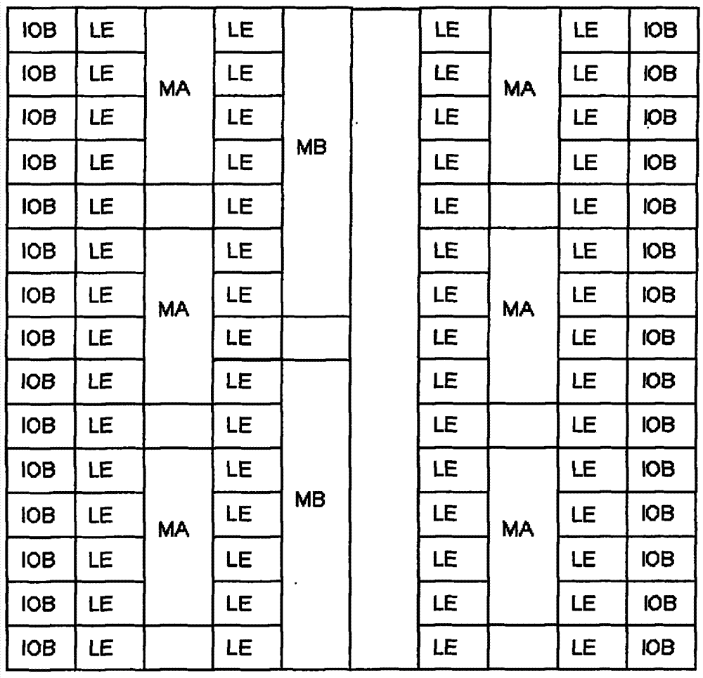
[0028] figure 1 It is a schematic diagram of a column structure FPGA. This type of FPGA has been used by many famous FPGA manufacturers such as Alteral and Xilinx. exist figure 1 Among them, IOB (IO-Block): input and output module; LE (Logic Element): basic logic unit, which consists of look-up tables, registers, etc.; MA (Macro A): macro unit of type A; MB (Macro B) : A macrocell of type B.

[0029] The embodiments of the present invention are not only applicable to FPGAs with a column structure type, but also applicable to FPGAs of various heterogeneous types.

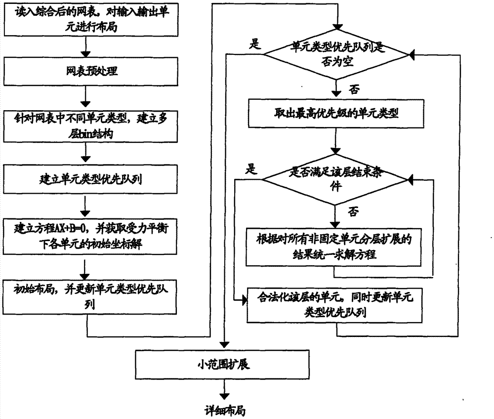
[0030] figure 2 It is a flowchart of a field programmable gate array layout method according to an embodiment of the present invention.

[0031] Step 1: Read in the synthesized netlist and lay out the input and output units. After synthesizing the design file into a gate-level circuit and analyzing it, then the peripheral input and output units ( figure 1 IOB in ) for layout. Use the random layout method com...


PUM


Abstract

The invention discloses a layout method for a heterogeneous field programmable gate array (FPGA). The method comprises the following steps of: laminating different unit types; applying force onto a priority level in a laminated way according to the different unit types; and solving all movable units uniformly. Compared with the conventional FPGA layout algorithm, the layout method has the advantages that: the operation time of the FPGA is reduced; simultaneously, the design performance of the FPGA is improved.

Description

technical field [0001] The invention relates to the field of integrated circuits, in particular to a layout method of a field programmable gate array. Background technique [0002] Field Programmable Gate Array (Field Programmable Gate Array, FPGA) is a product of further development on the basis of programmable devices. It appeared as a semi-custom circuit in the field of application-specific integrated circuits, which not only solved the shortcomings of full-custom circuits, but also overcome the shortcomings of the limited number of original programmable device gate circuits. [0003] In the layout design of FPGA, the rationality of the layout has a great influence on the actual performance of the final FPGA chip. The traditional FPGA layout algorithm runs slowly when dealing with netlists of mixed cells (heterogeneous forms), and the final performance is low. For circuits with high delay requirements, it is difficult to meet the design requirements. For traditional het...

Claims


Application Information

Patent Timeline
Patent Type & Authority Patents(China)
IPC IPC(8): G06F17/50
Inventor 刘攀王海力孙亚强
Owner AGATE LOGIC BEIJING
Learn More