A Method for Optimal Arrangement of Flow and Pressure Monitoring Points in Heating Pipe Network
A heat supply network and pressure monitoring technology, applied in forecasting, data processing applications, instruments, etc., can solve the problems of lack of heat supply network flow and reasonable arrangement of pressure monitoring points, etc., to improve the accuracy of the hydraulic model of the heat network , high practicability, easy to use
- Summary
- Abstract
- Description
- Claims
- Application Information
AI Technical Summary
Problems solved by technology
Method used
Image
Examples
specific Embodiment approach 1
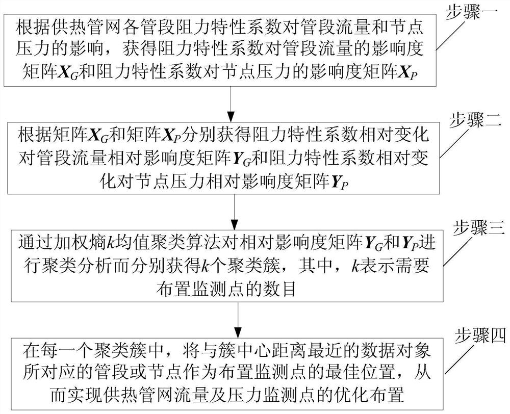
[0015] Specific implementation mode one: refer to figure 1 Specifically explaining this embodiment, a method for optimizing the arrangement of flow and pressure monitoring points in a heating pipe network described in this embodiment includes the following steps:
[0016] Step 1. According to the influence of the resistance characteristic coefficient S of each pipe section in the heating pipe network on the pipe flow and node pressure, obtain the influence degree matrix X of the resistance characteristic coefficient on the pipe flow G and the influence degree matrix X of the resistance characteristic coefficient on the nodal pressure P ;
[0017] Step 2. According to the matrix X G and matrix X P Obtain the matrix Y of the relative influence degree of the relative change of the resistance characteristic coefficient on the flow rate of the pipe section respectively G and the relative change of the resistance characteristic coefficient on the relative influence degree matrix...
Embodiment 1
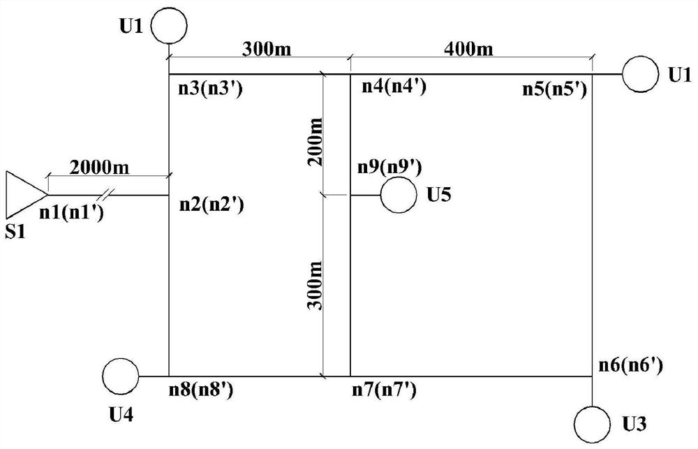
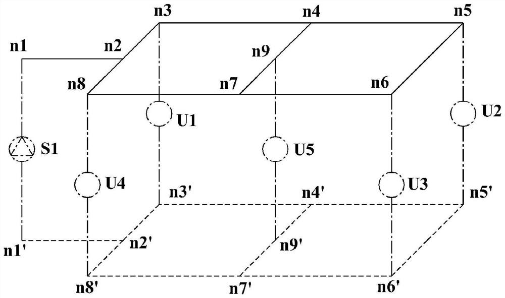
[0021] Assume that an ideal space heating system includes 1 heat source and 5 heat stations, and the plan and topology of the heating pipe network are as follows: figure 2 and image 3 As shown, the numbers in the brackets indicate the return water nodes, and the numbers outside the brackets indicate the water supply nodes. The heating pipe network has 18 nodes and 26 pipes in total, that is, n=17, b=26. The design and operating parameters of the heating pipe network are shown in Table 1. The characteristic equation of the circulating water pump is dh=-0.3125g 2 +100g+9.42×10 5 , where dh is the head of the pump, Pa; g is the circulation flow of the pump, t / h.
[0022] Table 1 Design and operation parameters of heating pipe network
[0023]
[0024] According to the design and operation parameters of the heating pipe network in Table 1, calculate the relative influence matrix Y of the relative change of the resistance characteristic coefficient on the flow of the pipe...
specific Embodiment approach 2
[0025] Specific embodiment 2: This embodiment is to further explain the method for optimizing the layout of flow and pressure monitoring points of a heating pipe network described in specific embodiment 1. In this embodiment, in step 1, the resistance characteristic coefficient is obtained for the pipe section Traffic influence matrix X G and the influence degree matrix X of the resistance characteristic coefficient on the nodal pressure P The specific process:
[0026] Assuming that a heating pipe network has n+1 nodes and b pipe sections, the identification model of the resistance characteristic coefficient of the heating pipe network is expressed as:
[0027]
[0028] In the formula, A is the basic correlation matrix, n×b matrix, A T is the transposition matrix of the basic correlation matrix, b×n matrix, G is the column vector of pipe mass flow rate, b×1 column vector, G diag is the diagonal matrix of the mass flow rate of the pipe section, b×b diagonal matrix, Q is ...
PUM
 Abstract
Description
Claims
Application Information
 - R&D
- Intellectual Property
- Life Sciences
- Materials
- Tech Scout
- Unparalleled Data Quality
- Higher Quality Content
- 60% Fewer Hallucinations
Browse by: Latest US Patents, China's latest patents, Technical Efficacy Thesaurus, Application Domain, Technology Topic, Popular Technical Reports.
© 2025 PatSnap. All rights reserved.Legal|Privacy policy|Modern Slavery Act Transparency Statement|Sitemap|About US| Contact US: help@patsnap.com


