
Voltage stabilizing device without harmonic pollution or instantaneous output voltage sag and voltage stabilizing method

A voltage stabilizing device and output voltage technology, which can be used in the direction of conversion equipment, transformers/inductor coils/windings/connections that can be converted to direct current without intermediate conversion, and can solve problems such as output voltage drops

Active Publication Date: 2012-03-14
XIAN ACTIONPOWER ELECTRIC
View PDF4 Cites 3 Cited by
  • Summary
  • Abstract
  • Description
  • Claims
  • Application Information

AI Technical Summary

Problems solved by technology

[0005] The purpose of the present invention is to provide a voltage stabilizing device and a voltage stabilizing method without harmonic pollution and instantaneous output voltage drop in order to solve the problems of harmonic feedback and instantaneous large drop of output voltage in the process of switch switching in the prior art

Method used


Image

  • Voltage stabilizing device without harmonic pollution or instantaneous output voltage sag and voltage stabilizing method
  • Voltage stabilizing device without harmonic pollution or instantaneous output voltage sag and voltage stabilizing method

Examples


Embodiment Construction

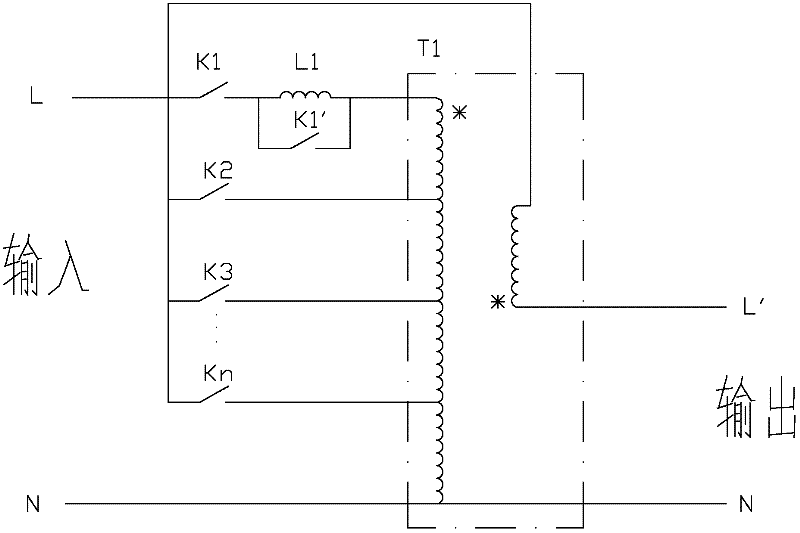
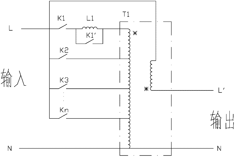
[0021] The voltage stabilizing device is composed of switches K1-Kn, inductance L1 connected with switch K1', and primary-side multi-tap transformer T1.

[0022] When the voltage stabilizing device works in a steady state, one of the switches in K1 ~ Kn is closed and the others are opened to obtain the corresponding compensation voltage. In steady state, the switch state of K1' is the same as that of K1.

[0023] During the gear switching process of the voltage stabilizing device, the system switching sequence is as follows:

[0024] Timing one:

[0025] Assuming that the initial state of the system is in the closed state of switches K1 and K1′, it needs to be switched to the closed state of Ka (a≠1, a≤n), and the switching sequence is as follows:

[0026] ① K1, K1' are closed, Ka is open

[0027] ② K1' disconnected (K1 closed, K1', Ka disconnected)

[0028] ③Ka closed (K1, Ka closed, K1'opened)

[0029] ④ K1 is disconnected (Ka is closed, K1, K1' are disconnected)

[00...


PUM


Abstract

The invention relates to a voltage stabilizing device without harmonic pollution or instantaneous output voltage sag and a voltage stabilizing method. The device is formed by connecting switches K1-Kn, an inductor L1, a switch K1' and a primary side multi-tap transformer T1. Because the inductor L1 and the switch K1' are used in the device, the output voltage can still be stably output in the switching process in a specified system switching time sequence, instantaneous sag is not produced, and the device and the method meet the requirements of certain equipment sensitive to instantaneous voltage sag, particularly the occasions of high power.

Description

technical field [0001] The patent of the present invention relates to the technical field of voltage regulators, in particular to a high-power voltage regulator sensitive to instantaneous voltage drop index requirements. Background technique [0002] Most of the voltage stabilizers on the existing market are silicon controlled rectifier phase-shift voltage regulation type and combined compensation type. [0003] The thyristor phase-shift voltage regulator adopts the method of controlling the conduction angle of the thyristor to change the compensation voltage of the voltage regulator. At this time, the thyristor will generate a large number of harmonics and feed back to the power grid during the conduction process. , in high-power applications, it will have a great impact on the normal operation of other equipment; [0004] The combined compensation voltage stabilizer adopts switching mode to stabilize the voltage. During the switching process, the compensation transformer ...

Claims


Application Information

Patent Timeline
Patent Type & Authority Applications(China)
IPC IPC(8): H02M5/32H02M5/10H01F27/28
Inventor 卢家林王昆
Owner XIAN ACTIONPOWER ELECTRIC
Learn More