


Quick Research
Generate reliable direction feasibility study reports for your R&D in just a few steps.

Technical Q&A
Discover and master advanced knowledge NOW. Basics, ideas, possibilities, all at once.

Find Solutions
As an expert in R&D theories, this can generate solutions to your technical problems instantly.

Evaluate Feasibility
Analyze your overall solution with one click, know your potential R&D risks in advance.

Monitor Landscape
Get weekly tech updates, stay abreast of the latest tech innovations and key insights.
Bellows type mechnical seal
A technology of mechanical seals and bellows, which is applied in the direction of engine seals, mechanical equipment, engine components, etc., can solve the problems of damage to bellows 101, and achieve the effect of reducing impact and inhibiting damage
- Summary
- Abstract
- Description
- Claims
- Application Information
AI Technical Summary
Problems solved by technology
Method used
Image


Examples
Embodiment 1
[0056] refer to figure 1 , the bellows type mechanical seal according to Embodiment 1 of the present invention will be described. figure 1 It is a schematic cross-sectional view illustrating the structure of the bellows-type mechanical seal in Embodiment 1 of the present invention.
[0057] The bellows-type mechanical seal 1 of this embodiment is used in petroleum refining, petrochemical equipment, iron-making chemical equipment, etc., for treating fluids with a high temperature exceeding 200°C and containing many solid components, such as asphalt, tar, or asphalt. Pump shaft seal.
[0058] The general structure of the bellows type mechanical seal 1 is to seal the shaft hole 21 of the housing 20 and the rotating shaft 30 by sealing the seal ring 12 in sealing contact with the adapter ring 13 fixed to the rotating shaft 30 and the stopper 14 respectively. The annular gap, wherein the stopper 14 is elastically supported on the housing 20 via the bellows 11, the collar 15, th...
Embodiment 2
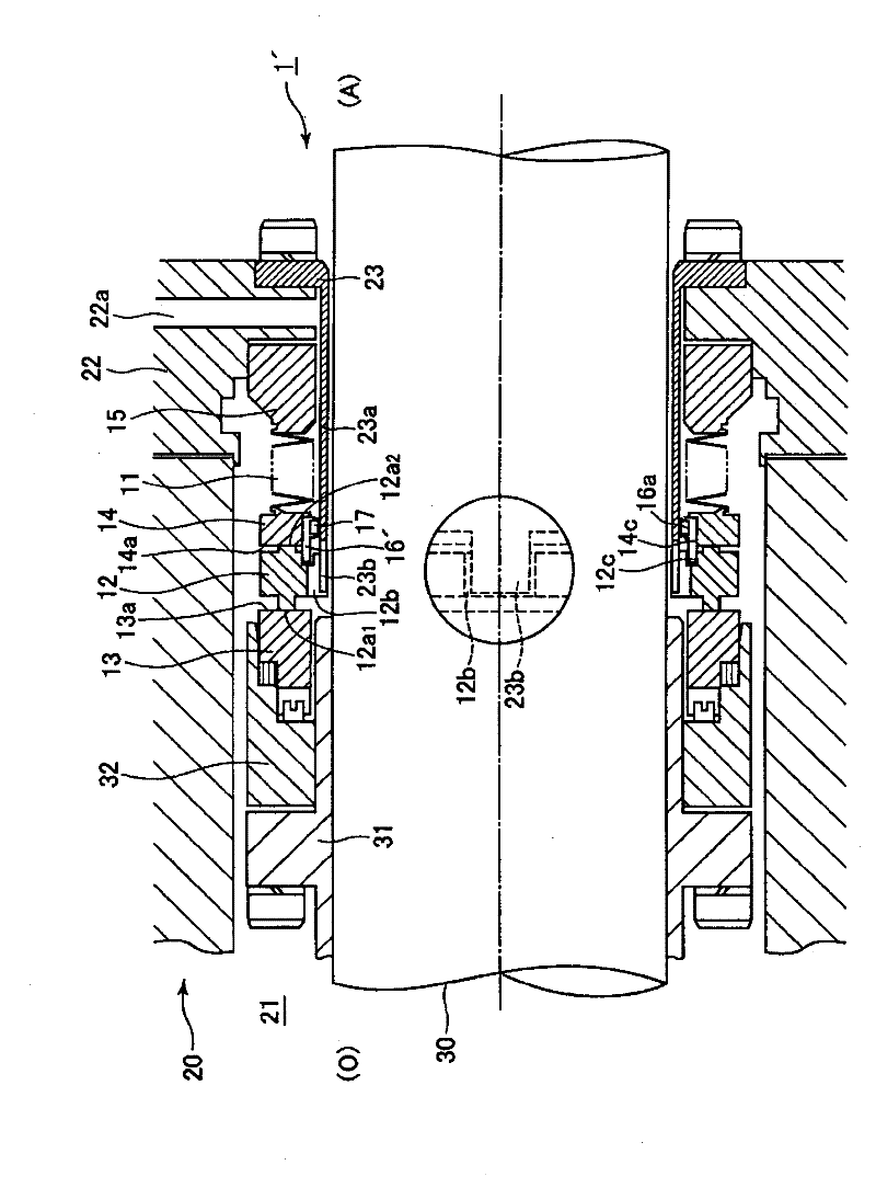
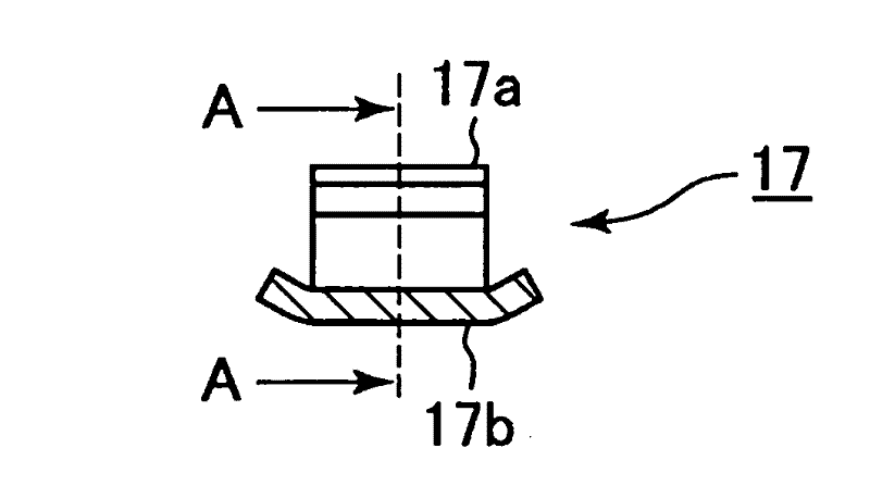
[0075] refer to Figure 2 ~ Figure 3B , the bellows-type mechanical seal 1' according to the second embodiment of the present invention will be described. figure 2 It is a schematic cross-sectional view illustrating the structure of a bellows-type mechanical seal 1' according to Embodiment 2 of the present invention. Figure 3A and Figure 3B A schematic diagram illustrating the structure of the elastic member, Figure 3A is a schematic cross-sectional view of the elastic component, Figure 3B for Figure 3A Sectional view of direction A. Here, the same reference numerals are assigned to the same structures as in the above-mentioned first embodiment, detailed description thereof will be omitted, and only the differences from the first embodiment will be described. The unexplained structures are the same as those in Example 1.
[0076] This embodiment includes an elastic member 17 that applies elastic force to the stopper 14 in the outer diameter direction. The elastic ...
Embodiment 3
[0082] refer to Figure 4 A bellows-type mechanical seal 1" of Embodiment 3 of the present invention will be described. Figure 4 It is a schematic cross-sectional view illustrating the structure of the bellows-type mechanical seal 1"' of Embodiment 3 of the present invention. Here, for the same structures as the above-mentioned embodiments, the same symbols are attached, and detailed descriptions are omitted. Only the above-mentioned The parts that are different from the embodiments will be described. The structures that are not described are the same as those of the above-mentioned embodiments.
[0083] In this embodiment, an annular groove 14d is provided on the inner peripheral side of the stopper 14', and the elastic member 17 is attached to the annular groove 14d. That is, compared to the aforementioned embodiment 2, which damps the vibration of the sealing ring 12 and the stopper 14 via the centering housing 16 ′, this embodiment uses the elastic member 17 to directly ...
PUM
 Abstract
Description
Claims
Application Information
 - R&D Engineer
- R&D Manager
- IP Professional
- Industry Leading Data Capabilities
- Powerful AI technology
- Patent DNA Extraction
Browse by: Latest US Patents, China's latest patents, Technical Efficacy Thesaurus, Application Domain, Technology Topic, Popular Technical Reports.
© 2024 PatSnap. All rights reserved.Legal|Privacy policy|Modern Slavery Act Transparency Statement|Sitemap|About US| Contact US: help@patsnap.com