Method for securing the operation of an electric battery

A battery safety and working technology, applied in thermal engine, highly hybrid thermal vehicle, battery field, can solve the problem of medical personnel contact and so on

Inactive Publication Date: 2012-03-14
DOW KOKAM FRANCE
View PDF0 Cites 1 Cited by
  • Summary
  • Abstract
  • Description
  • Claims
  • Application Information

AI Technical Summary

Problems solved by technology

In fact, regardless of the state of the contactor, high voltages are maintained between electrically connected battery elements and could lead to contact of medical personnel with these voltage sources

Method used


Image

  • Method for securing the operation of an electric battery
  • Method for securing the operation of an electric battery
  • Method for securing the operation of an electric battery

Examples


Embodiment Construction

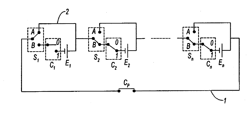
[0038] Referring to these drawings, the following describes a battery including a plurality of power generating elements E installed in the power generating circuit 1 . More specifically, the electrochemical nature of the element E may be of the Li-ion or Li-polymer type to generate the required energy.

[0039] Each element E is housed in a hermetic envelope with two terminals (anode and cathode) respectively for connecting said element to the generating circuit 1 . In the envelope, there is provided a stack or winding of electroactive layers acting respectively as anode and cathode, said layers being contacted by an electrolyte. The layers may be contained within a flexible envelope. Alternatively, they may also be housed in rigid containers.

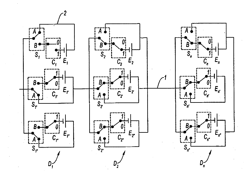
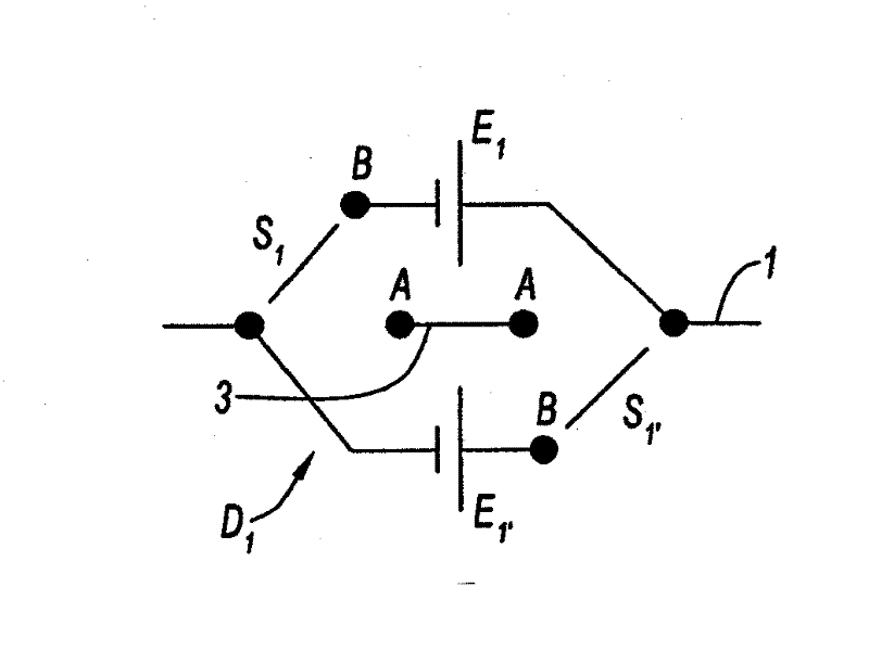
[0040] according to figure 1 The first embodiment shown, element E 1 -E n Installed in series in generating circuit 1. In the second embodiment, the battery includes a plurality of cells D mounted in series in the generating cir...


PUM


Abstract

The invention relates to a method for securing the operation of an electric battery including a plurality of elements (E) generating electric power which are mounted in a circuit (1) for the producing electricity, said method including checking for an appearance of a malfunction in each of said elements and, in the event of detecting a malfunction of an element (E), shunting said malfunctioning element such that the electric current no longer passes through said malfunctioning element while keeping the production circuit (1) closed. The invention also relates to a battery in which such a method can be implemented.

Description

technical field [0001] The invention relates to a method of ensuring safe operation of a battery and a battery capable of performing such a method. [0002] The battery according to the invention is used in particular for the traction of electric or hybrid vehicles, that is to say comprising an electric motor for driving the driving wheels, in combination with a heat engine for driving these or possibly other driving wheels. [0003] More specifically, the invention is applicable to highly hybrid thermal vehicles enabling full electrification of the traction chain. In this case, the battery not only assists the vehicle during the acceleration phase, but also provides autonomous movement of the vehicle over longer or shorter distances. [0004] The battery according to the invention can also be used in other technical fields, for example in the storage of electrical energy for other modes of transport, especially in the field of aviation. Furthermore, the method of securing b...

Claims


Application Information

Patent Timeline
Patent Type & Authority Applications(China)
IPC IPC(8): H02J7/00
CPCH02J7/0016H02J7/0031B60L58/10Y02T10/70H02J7/00309H02J7/00306H02J7/00H02H7/18
Inventor 法比·加邦
Owner DOW KOKAM FRANCE
Why Eureka
Try Eureka