Oil buffer

A technology of oil pressure buffers and oil cylinders, applied in the field of oil pressure buffers, can solve problems such as deepening, harsh well dimensions, and increased well construction costs, and achieve the effects of reducing overall height, lowering requirements, and fine control

Active Publication Date: 2012-03-21
HITACHI ELEVATOR CHINA
View PDF4 Cites 7 Cited by
  • Summary
  • Abstract
  • Description
  • Claims
  • Application Information

AI Technical Summary

Problems solved by technology

Therefore, because the height of this buffer is too high, the depth of the shaft pit where the buffer is installed must be correspondingly deepened, which will impose more stringent requirements on the size of the shaft and increase the construction cost of the shaft

Method used


Image

  • Oil buffer
  • Oil buffer
  • Oil buffer

Examples


Embodiment Construction

[0025] Embodiments of the present invention will be described in detail below.

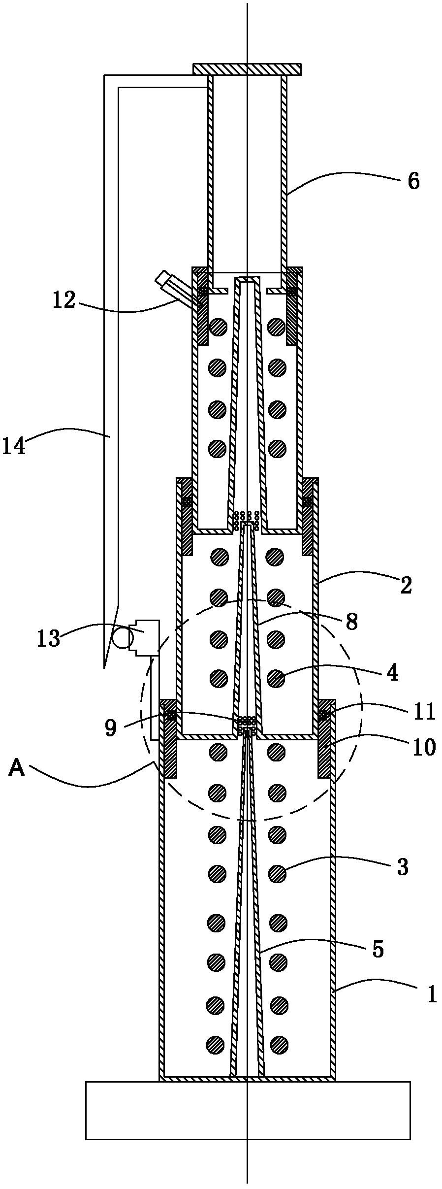
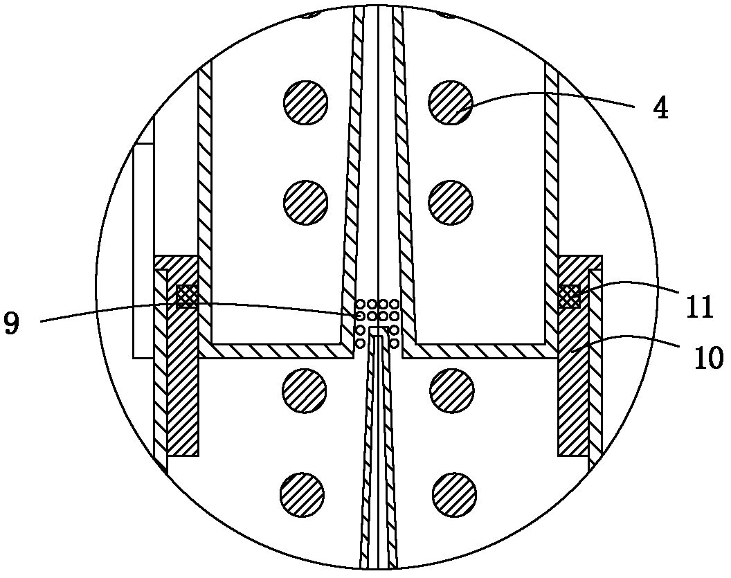
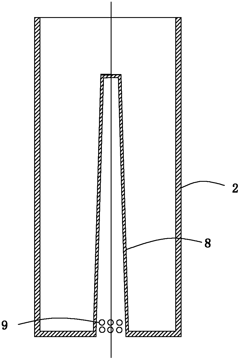
[0026] Please refer to Figure 1 to Figure 5 An oil pressure buffer, including an oil cylinder 1, a first plunger 2, a first elastic member 3, a second elastic member 4, and a second plunger 6, the first plunger 2 is sleeved on the surface of the oil cylinder 1, and the second The plunger 6 is sleeved on the surface of the first plunger 2, the first elastic member 3 is arranged between the oil cylinder 1 and the first plunger 2, and the second elastic member 4 is arranged on the first plunger 5 and the second plunger 6 Between them, the first plunger 5 and the second plunger 6 open a plunger oil hole 7 . In this embodiment, the oil pressure buffer includes two first plungers 2 and two second elastic components 4 . One end of one of the first plungers 2 is sleeved with the oil cylinder 1 , and one end of the other first plunger 2 is sleeved with the second plunger 6 , and the two first plungers 2...


PUM


Abstract

The invention discloses an oil buffer, which comprises an oil cylinder, a first plunger, a first elastic part, a second elastic part, and a second plunger, wherein the first plunger is sleeved on the surface of the oil cylinder; the second plunger is sleeved on the surface of the first plunger; the first elastic part is arranged between the oil cylinder and the first plunger; the second elastic part is arranged between the first plunger and the second plunger; and the first plunger and the second plunger are provided with plunger oil holes. The whole height of the buffer is greatly reduced, and the depth of a well pit is reduced.

Description

technical field [0001] The invention relates to an oil pressure buffer. Background technique [0002] Most of the existing energy-consuming hydraulic buffers produced at home and abroad use an oil cylinder, a plunger barrel, and a tapered column as the main components, and use the damping force of the liquid flow to slow down the impact of the car when it falls, and use the spring to make the car fall. its reset. The basic principle is that when a heavy object falls from a height and hits the buffer, the plunger moves downward, compressing the oil in the cylinder so that the oil overflows into the plunger barrel through the annular hole on the end cover of the plunger. In the process of stopping the heavy object, its kinetic energy is converted into the heat energy of the oil, which makes the heavy object decelerate and stop. Since most of the traditional hydraulic buffers adopt a single-stage structure of an oil cylinder and a plunger barrel, the compression stroke of the...

Claims


Application Information

Patent Timeline
Patent Type & Authority Applications(China)
IPC IPC(8): B66B5/28
Inventor 刘建军
Owner HITACHI ELEVATOR CHINA
Why Eureka
Try Eureka