Electrolytic regeneration treatment device
A treatment device and electrolytic regeneration technology, which is applied in the secondary treatment of printed circuits, electrolytic process, electrolytic components, etc., can solve the problems of enlarging electrolytic regeneration tanks, large quantities, etc., and achieve the effect of reducing liquid volume
- Summary
- Abstract
- Description
- Claims
- Application Information
AI Technical Summary
Problems solved by technology
Method used
Image

Examples
no. 1 Embodiment approach >
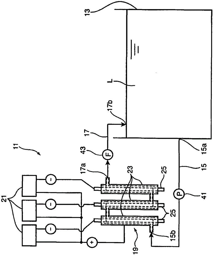
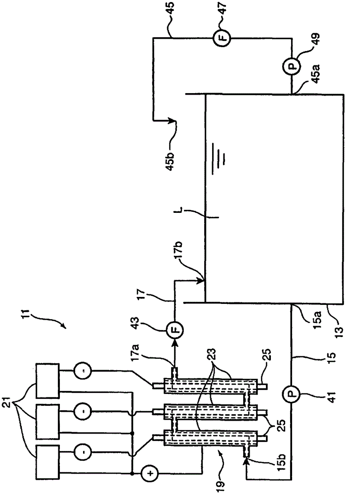
[0024] Such as figure 1 As shown, the electrolytic regeneration treatment device 11 according to the first embodiment of the present invention electrolyzes the treatment solution in order to reuse the treatment solution after the desmear treatment in the process of manufacturing printed circuit boards for the removal of the smear. And the treatment liquid is regenerated. Hereinafter, a case where a solution of a permanganate such as sodium permanganate or potassium permanganate is used as the treatment liquid L will be described as an example. The treatment liquid L is stored in the desmear treatment tank 13 .
[0025] A resin substrate (not shown) constituting the substrate portion of the printed circuit board is immersed in the treatment liquid in the desmear treatment bath 13 to perform desmear treatment. According to this, the smear existing in the through hole or the via hole of the resin substrate is oxidized by the treatment liquid L, thereby removing the smear from t...
no. 2 Embodiment approach >
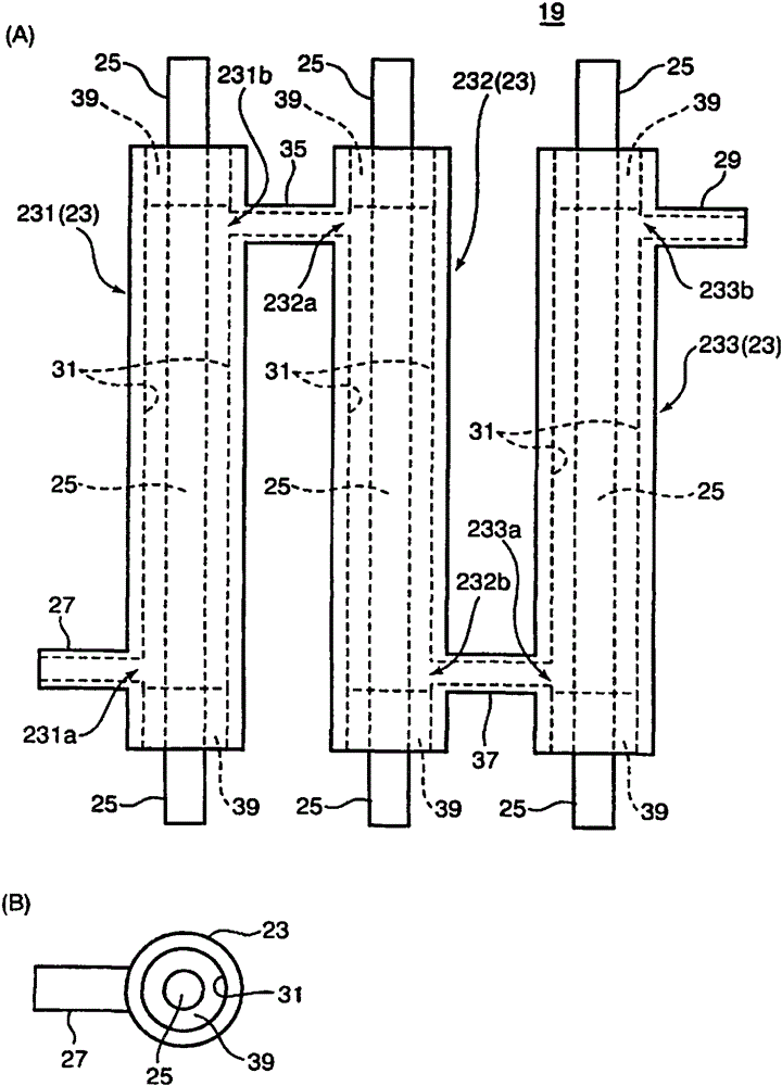
[0061] Next, the electrolytic regeneration treatment device 11 according to the second embodiment of the present invention will be described. Figure 5 It is a schematic diagram showing the regeneration processing unit 19 of the electrolytic regeneration processing device 11 according to the second embodiment. In the electrolytic regeneration treatment device 11 of the second embodiment, the configuration other than the regeneration treatment unit 19 is the same as that of the first embodiment, and thus description thereof will be omitted.
[0062] In this second embodiment, the treatment liquid L flowing through the delivery-side conduit 15 is guided to the upstream end 231 a of the first pipe 231 , the upstream end 232 a of the second pipe 232 , and the upstream of the third pipe 233 . side end portion 233a. In addition, the treatment liquid L flows from the upstream side to the downstream side in the flow path in each pipe 23, and flows from the downstream end portion 231b...
no. 3 Embodiment approach >
[0070] Image 6 It is a schematic diagram showing the regeneration processing unit 19 of the electrolytic regeneration processing device 11 according to the third embodiment of the present invention. Such as Image 6 As shown, the electrolytic regeneration treatment device 11 of the third embodiment includes a regeneration treatment unit 19 , an upstream side branch pipe 234 , a downstream side branch pipe 235 , and on-off valves 61 and 62 . The regeneration unit 19 includes a first piping unit 191 , a second piping unit 192 , and a third piping unit 193 . Each piping assembly has a Figure 4 The regeneration processing section 19 shown has the same structure. details as follows.
[0071] The first pipe assembly 191 includes three pipes 231 , 232 , and 233 as cylindrical portions, and a total of three cathodes 25 each provided one in each pipe. The three pipes of the first pipe unit 191 are the first upstream pipe 231 , the central first pipe 232 , and the downstream firs...
PUM
 Abstract
Description
Claims
Application Information
 - R&D Engineer
- R&D Manager
- IP Professional
- Industry Leading Data Capabilities
- Powerful AI technology
- Patent DNA Extraction
Browse by: Latest US Patents, China's latest patents, Technical Efficacy Thesaurus, Application Domain, Technology Topic.
© 2024 PatSnap. All rights reserved.Legal|Privacy policy|Modern Slavery Act Transparency Statement|Sitemap