Pneumatic valve

A technology of pneumatic valves and valve bodies, applied in valve details, valve devices, engine components, etc., can solve problems such as rigid opening and closing, and achieve the effects of easy installation and maintenance, simple structure, and large sealing area

Inactive Publication Date: 2012-03-21
TONGLING XIANGYUN FIRE FIGHTING TECH
View PDF3 Cites 1 Cited by
  • Summary
  • Abstract
  • Description
  • Claims
  • Application Information

AI Technical Summary

Problems solved by technology

[0003] The purpose of the present invention is to provide a pneumatic valve to solve the problem of rigid opening and closing of the existing pneumatic valve structure

Method used


Image

  • Pneumatic valve
  • Pneumatic valve

Examples


Embodiment Construction

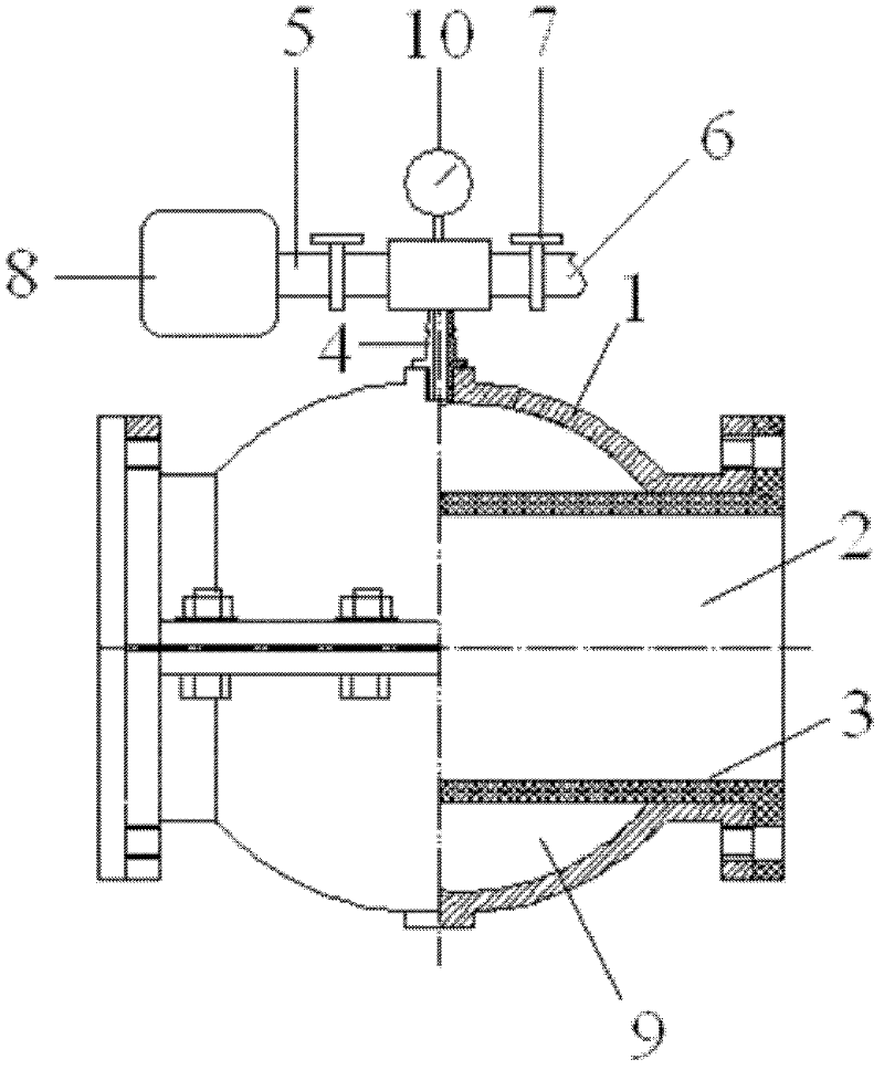
[0010] see figure 1 , a pneumatic valve, including a valve body 1, the middle of the valve body 1 has a fluid channel 2, the two ends of the fluid channel 2 are respectively inlet and outlet, the fluid channel 2 is provided with a rubber tube 3, and the two ends of the rubber tube 3 It is sealingly connected with the inner wall of the valve body 1, and the side wall of the valve body 1 is provided with a vent 4 and is respectively externally connected with an intake pipe 5 and an exhaust pipe 6, and a control valve 7 is respectively installed in the intake pipe 5 and the exhaust pipe 6, The air intake pipe 5 is externally connected to an air source 8; there is a gap between the valve body 1 and the rubber tube 3 and forms an airtight air bag 9.

[0011] Further, a pressure gauge 10 is installed on the intake pipe 5 or the exhaust pipe 6 for measuring the air pressure in the valve body 1 .

[0012] The air source 8 inflates the valve body 1 through the intake pipe 5, and the a...


PUM


Abstract

The invention discloses a pneumatic valve, which comprises a valve body. A fluid passage is arranged in the middle of the valve body, two ends of the fluid passage are an inlet and an outlet respectively, a rubber pipe is arranged in the fluid passage, two ends of the rubber pipe are in sealing connection with the inner wall of the valve body, air ports are arranged on the lateral wall of the valve body and are respectively in external connection with an air inlet pipe and an air outlet pipe, a control valve is respectively installed in the air inlet pipe and the air outlet pipe, and the air inlet pipe is in external connection with an air source. A gap is arranged between the valve body and the rubber pipe, and a sealed air bag is formed. The pneumatic valve is simple and compact in structure, large in sealing area, convenient to operate, easy to install and maintain and long in service life, and has good practical value.

Description

technical field [0001] The invention relates to a pneumatic valve. Background technique [0002] Valves are widely used in industrial and agricultural production. Existing air control valves are mainly composed of pneumatic actuators, control pipelines and valves. Its actuator mainly drives the butterfly plate or ball valve spool or other corresponding mechanisms to perform rigid opening and closing operations through the reciprocating motion of the cylinder, which makes the sealing parts easy to be damaged by friction, and the complex structure makes it difficult to replace the seals. Contents of the invention [0003] The purpose of the present invention is to provide a pneumatic valve to solve the problem of rigid opening and closing of the existing pneumatic valve structure. [0004] Technical scheme of the present invention is as follows: [0005] A pneumatic valve includes a valve body, the middle part of the valve body has a fluid channel, and the two ends of...

Claims


Application Information

Patent Timeline
Patent Type & Authority Applications(China)
IPC IPC(8): F16K31/122F16K43/00
Inventor 何益庆
Owner TONGLING XIANGYUN FIRE FIGHTING TECH
Why Eureka
Try Eureka