
Flat tube discharging device

A discharge device and flat tube technology, which is applied in the directions of loading/unloading, transportation and packaging, and unstacking of objects, can solve the problems of high production cost of circular rolling discs, slow discharge speed of flat tubes, and reduced work efficiency, etc., to achieve Reduced labor and maintenance costs, fast discharge speed, and low production costs

Pending Publication Date: 2020-01-07
SHANGHAI HEKE EQUIP MFG
View PDF0 Cites 1 Cited by
  • Summary
  • Abstract
  • Description
  • Claims
  • Application Information

AI Technical Summary

Problems solved by technology

Due to the reciprocating movement of the feeding component or the circular roller on the flat tube, it is easy to cause friction damage to the flat tube, which makes the discharge speed of the flat tube slower and reduces the work efficiency, and the production cost of the circular roller is higher

Method used


Image

  • Flat tube discharging device
  • Flat tube discharging device

Examples


Embodiment Construction

[0033] All features disclosed in this specification, or steps in all methods or processes disclosed, may be combined in any manner, except for mutually exclusive features and / or steps.

[0034] Any feature disclosed in this specification, unless specifically stated, can be replaced by other alternative features that are equivalent or have similar purposes. That is, unless expressly stated otherwise, each feature is one example only of a series of equivalent or similar features. Throughout the specification, like reference numerals refer to like elements.

[0035] In order to make the technical problems solved by the present invention, the technical solutions adopted and the technical effects achieved clearer, the technical solutions of the present invention will be further described below in conjunction with the accompanying drawings and through specific implementation methods.

[0036] This embodiment proposes a flat tube discharge device, which can discharge the flat tubes ...


PUM


Abstract

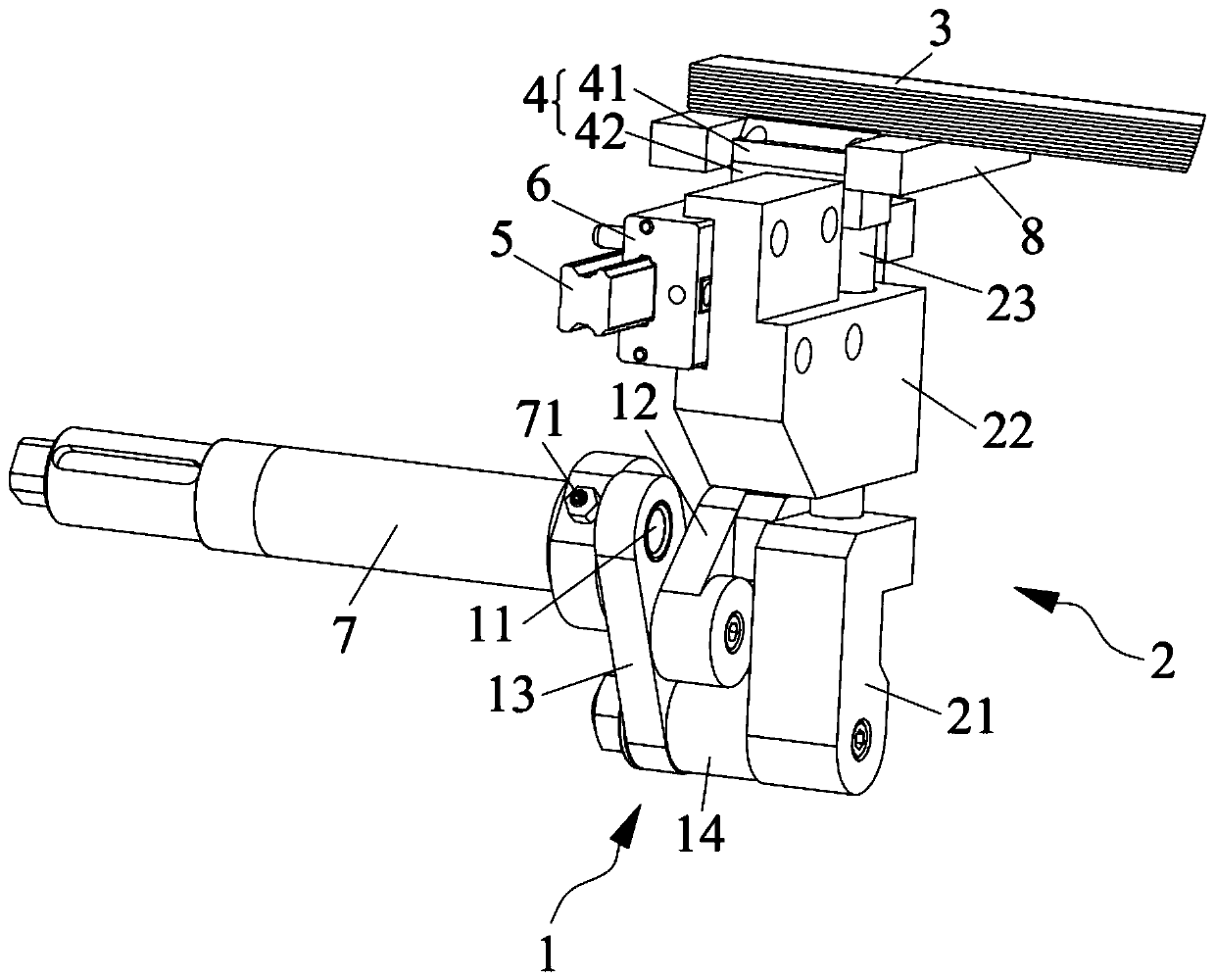
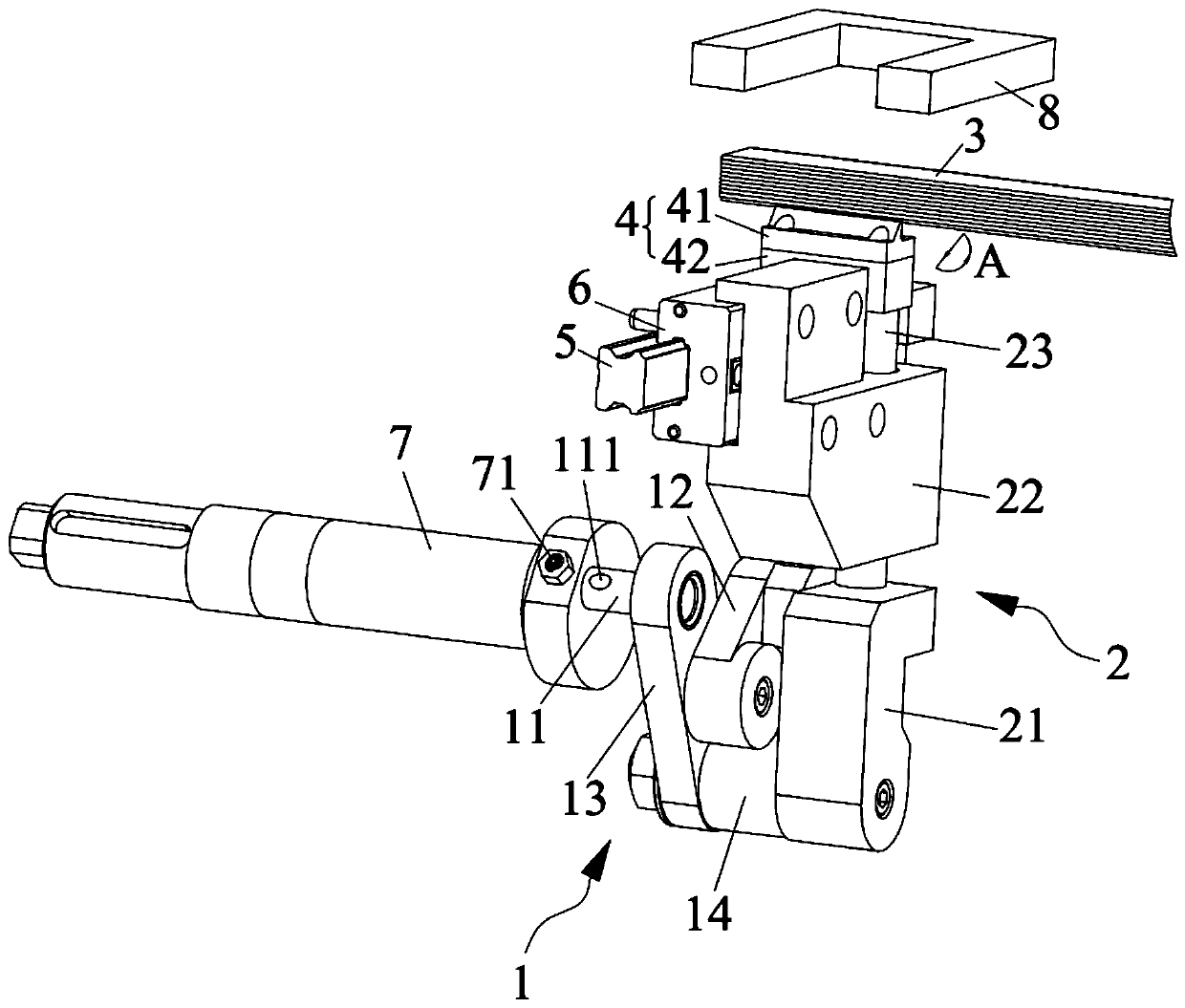
The invention discloses a flat tube discharging device and belongs to the technical field of heat exchanger flat tube production equipment. The flat tube discharging device comprises a driving part, aknockout assembly and a middle connecting rod mechanism. The material beating assembly abuts against a flat tube to discharge the flat tube; one end of the middle connecting rod mechanism is in driving connection with the driving part, the other end of the middle connecting rod mechanism is connected with the knockout assembly, and the driving part drives the middle connecting rod mechanism to move so as to drive the knockout assembly to not make contact with the next flat tube after the knockout assembly discharges the flat tube and returns back to the original point. The flat tube discharging device has the beneficial effects that the middle connecting rod mechanism can drive the knockout assembly to move, so that the knockout assembly can be prevented from making contact with the nextflat tube in the process of returning to the original point, friction between the knockout assembly and the flat tube is avoided, and friction damage of the flat tube which is not discharged and the knockout assembly can be avoided at the same time.

Description

technical field [0001] The invention relates to the technical field of heat exchanger flat tube production equipment, in particular to a flat tube discharge device. Background technique [0002] Flat tube heat exchanger is an energy-saving equipment that realizes heat transfer between materials between two or more fluids at different temperatures. It transfers heat from a higher fluid to a lower temperature fluid, so that the fluid temperature reaches It is one of the main equipment to meet the requirements of the process conditions and improve the energy utilization rate at the same time. It can be mainly used in petroleum, chemical industry, metallurgy, electric power, shipbuilding, central heating, refrigeration and air conditioning, machinery, food and pharmaceutical fields. [0003] When the flat tube heat exchanger is assembled, the flat tubes are generally listed in the silo, and discharged one by one to the conveying worm through the discharge device, so as to facil...

Claims


Application Information

Patent Timeline
Patent Type & Authority Applications(China)
IPC IPC(8): B65G65/44B65G59/06B65G47/82
CPCB65G47/82B65G59/067B65G65/44B65G2201/022B65G2201/0276
Inventor 陈晓波刘一鸣邢加俊任志强
Owner SHANGHAI HEKE EQUIP MFG
Learn More