Power compensator charging capacitor power storage management system

A technology for charging capacitors and management systems, applied in current collectors, battery circuit devices, electric vehicles, etc., can solve the problem of high energy consumption, achieve fast discharge speed, reduce floor space, and avoid energy consumption.

Active Publication Date: 2017-11-17
CHONGQING DAJI ELECTRONICS TECH
View PDF9 Cites 5 Cited by
  • Summary
  • Abstract
  • Description
  • Claims
  • Application Information

AI Technical Summary

Problems solved by technology

[0004] The invention provides a power supply compensator charging capacitor power storage management system, which solves the problem in the prior art that the first supercapacitor voltage compensation unit and the second supercapacitor voltage compensation unit will supply power to each other, resulting in high energy consumption

Method used


Image

  • Power compensator charging capacitor power storage management system
  • Power compensator charging capacitor power storage management system
  • Power compensator charging capacitor power storage management system

Examples


Embodiment Construction

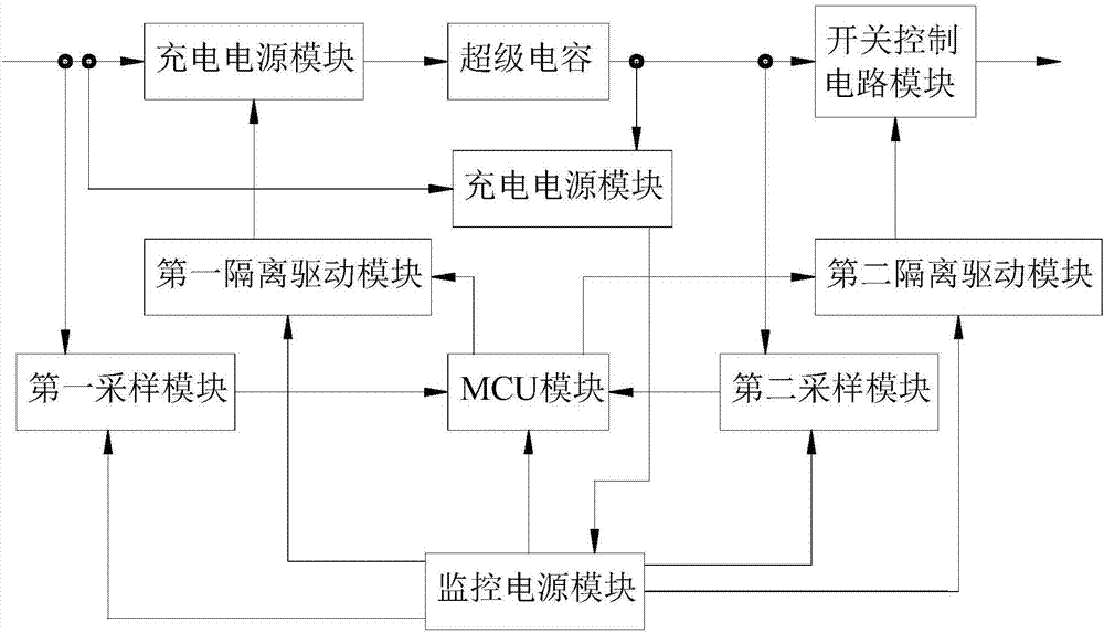
[0023] Such as figure 1As shown, the present invention proposes a power supply compensator charging capacitor power storage management system, including: a charging and discharging unit, which includes: a charging power module, a super capacitor and a switch control circuit module, and the input terminal of the charging power module is used to connect to Input power supply, the output terminal of the charging power supply module is connected to the positive pole of the super capacitor, the negative pole of the super capacitor is connected to the input terminal of the switch control circuit module, and the output terminal of the switch control circuit module is used to connect to the load; the monitoring unit includes: MCU module, the first sampling module, the second sampling module, the first isolated driving module, the second isolated driving module and the monitoring power supply module, the first output terminal of the monitoring power supply module is the MCU module, the ...


PUM


Abstract

The invention provides a power compensator charging capacitor power storage management system, which comprises a charge and discharge unit and a monitoring unit. The charge and discharge unit comprises a charging power supply module, a super capacitor and an on-off control circuit module. The input end of the charging power supply module is connected to an input power supply; the output end of the charging power supply module is connected to the positive pole of the super capacitor; the negative pole of the super capacitor is connected to the input end of the on-off control circuit module; and the output end of the on-off control circuit module is connected to a load. The monitoring unit comprises an MCU module, a first sampling module, a second sampling module, a first isolation driving module, a second isolation driving module and a monitoring power supply module. The charge and discharge unit also comprises a power switch module. The power compensator charging capacitor power storage management system solves the problem of high power consumption due to mutual power supply of a first super capacitor voltage compensation unit and a second super capacitor voltage compensation unit in the prior art.

Description

technical field [0001] The invention relates to a charging and discharging circuit, in particular to a power supply compensator charging capacitor storage management system. Background technique [0002] The Chinese patent discloses a ripple compensation circuit with the announcement number CN 102868287 B and a supercapacitor charging and discharging device. The ripple compensation circuit includes a charging voltage sampling unit on the grid side, which is used to sample the voltage input from the grid side when charging the supercapacitor. Real-time voltage; the charging voltage comparison unit is connected with the charging voltage sampling unit on the grid side, and is used to compare the real-time voltage with the preset standard charging voltage when charging the supercapacitor to obtain a charging voltage correction signal; the first supercapacitor The voltage compensating unit is connected with the charging voltage comparing unit, and is used for adjusting the voltag...

Claims


Application Information

Patent Timeline
Patent Type & Authority Applications(China)
IPC IPC(8): H02J7/00H02J7/34
CPCH02J7/0086H02J7/345
Inventor 董俊峰周智宇莫桃秦士勇
Owner CHONGQING DAJI ELECTRONICS TECH
Why Eureka
Try Eureka