Protective device for electrical system box vent hole

A technology for electrical systems and protective devices, which is applied to the cooling/ventilation of substation/distribution device enclosures, electrical components, and substations/switchgear. Not good and other problems, to achieve the effect of good ventilation, firm fixation, and increased ventilation area

Inactive Publication Date: 2012-03-21
PINGGAO GRP
View PDF8 Cites 5 Cited by
  • Summary
  • Abstract
  • Description
  • Claims
  • Application Information

AI Technical Summary

Problems solved by technology

[0004] The purpose of the present invention is to provide a protective device for ventilation holes of electrical system boxes to solve the problems of insufficient protection level, weak assembly and fixation, and poor ventilation effect of the ventilation hole protective device in the prior art

Method used


Image

  • Protective device for electrical system box vent hole
  • Protective device for electrical system box vent hole
  • Protective device for electrical system box vent hole

Examples


Embodiment Construction

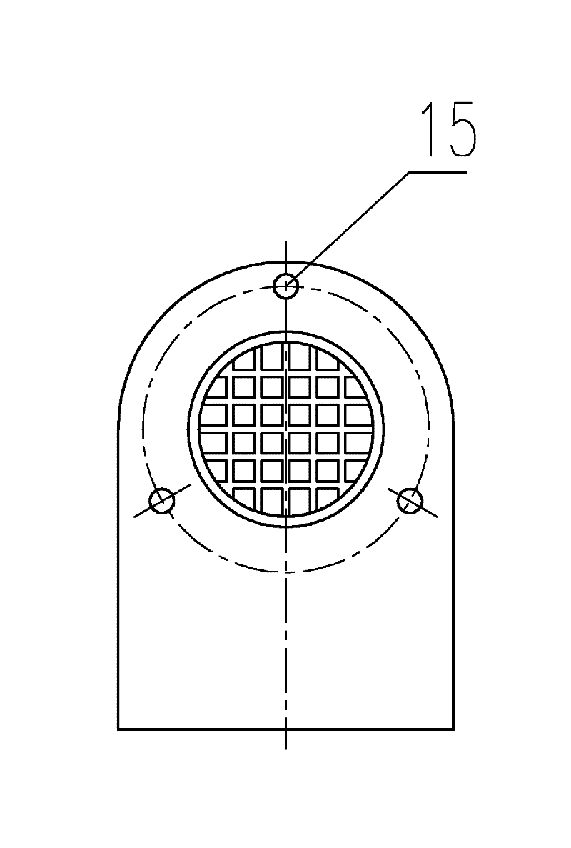
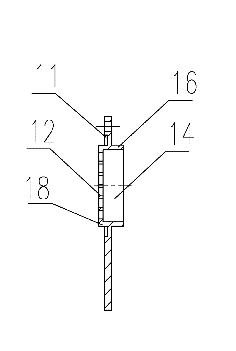
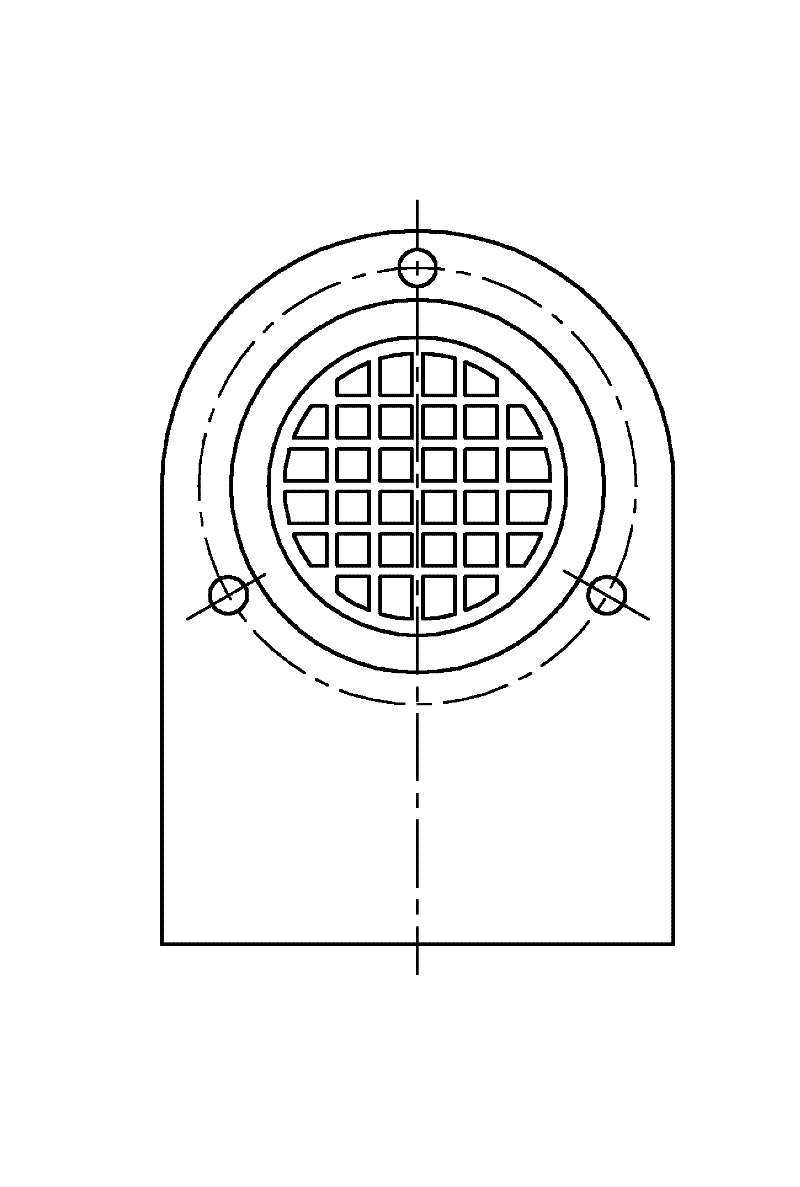
[0032] Embodiment 1 of a protective device for ventilation holes of an electrical system box body, such as Figure 1-Figure 6 As shown, the housing 2 in this embodiment is as Figure 4-5 As shown, it is a one-time molding structure, which includes a bridge plate 24 with a semicircular upper part, two side plates 25 located on both sides of the bridge plate and connected by the bridge plate, and an end plate that closes the two side plates and the rear end of the bridge plate 26. The front end of the shell 2 is provided with a eaves 27 protruding along the outer edge of the shell, and the bridging plate of the shell and the inner edge walls of the two side plates protrude respectively and are provided with assembly protrusions 21 for assembling. Threaded blind holes 23 are provided, and the shell seat 1 of embodiment 1, such as Figure 1-3 As shown, the housing base 1 has an outer edge surface that matches the shape of the inner edge surface of the eaves 27 of the housing 2. T...


PUM


Abstract

The invention discloses a protective device for an electrical system box vent hole. The protective device comprises a shell, wherein the shell comprises a bridging plate, two side plates which are arranged on the two sides of the bridging plate and are connected through the bridging plate, and an end plate which is used for sealing the rear ends of the two side plates and the bridging plate. The protective device is characterized in that the front end of the shell is provided with a shell seat, a communicating hole which is used to communicate with the vent hole is arranged on the shell seat, a dust screen which is used to seal the communicating hole is arranged on the shell, each inner edge wall of the bridging plate the two side plates of the shell is provided with at least one assembly bulge for assembling, the assembly bulges are provided with tapped blind holes, the parts of the shell seat, corresponding to the assembly bulges, are provided with assembly through holes. In the invention, since the shell seat is arranged between the shell and the outer wall of the box, a fixed structure is firmer; since assembly bulges are arranged on the inner edge walls of the bridging plate and the two side plates in a rasied manner, firmer assembly is achieved; meanwhile, the ventilation area of the protective device is increased so that the good ventilation effect can be reached; and since the dust screen is fixedly arranged on the shell seat the dust screen is fixed more firmly.

Description

technical field [0001] The invention relates to a protection device for ventilation holes of electrical system boxes, in particular to a protection device for ventilation holes of electrical system boxes such as a control cabinet, a distribution box, and a mechanism box. Background technique [0002] When the electrical system box is in use, if there is no requirement for forced ventilation, ventilation holes are generally used for heat dissipation and ventilation. There will be rainwater entering the box from the ventilation holes, which will bring safety hazards to the reliable operation of the equipment in the box. Therefore, the ventilation holes are the key protection objects. The national standard stipulates that the protection level of the above-mentioned boxes must reach IP54, so the protection of the ventilation holes The protection level of the device also needs to meet the national standard of IP54. [0003] At present, the usual method for dust prevention in the...

Claims


Application Information

Patent Timeline
Patent Type & Authority Applications(China)
IPC IPC(8): H02B1/56H02B1/28H02B1/46
Inventor 温铭丽林麟贺晶晶王赛豪周健武孙琼
Owner PINGGAO GRP
Why Eureka
Try Eureka