Sintering annular cooler pallet

A sintering ring cooler and ring cooler technology, applied in the furnace type, processing discharged materials, furnace and other directions, can solve the problems of increasing the air volume of the cooling fan, reducing the cooling effect of the ring cooler, and large air leakage rate, etc. Ventilation area, increased productivity, simple effect of sealing components

Active Publication Date: 2013-08-21
MCC NORTH (DALIAN) ENG TECH CO LTD
View PDF8 Cites 4 Cited by
  • Summary
  • Abstract
  • Description
  • Claims
  • Application Information

AI Technical Summary

Problems solved by technology

During the cooling process of sinter, due to the limitation of the structure, the steel plate above the triangular beam has no ventilation holes, and there are relatively few opportunities for the hot sinter on the upper part to exchange heat directly with the cooling air, which will affect the cooling effect of this part of the sinter, because The one-to-one correspondence between the triangular beam and the trolley, the gradual accumulation of several such effects will reduce the cooling effect of the entire ring cooler
In addition, since the trolley body of this structure is at the level of the cooling section and the unloading section is inclined, the sealing of the annular cooler cannot be continuous, which makes the overall sealing effect of the annular cooler unsatisfactory and the air leakage rate is too large
In order to achieve the ideal cooling effect, it is necessary to increase the air volume of the cooling fan, which will inevitably increase the energy consumption and affect the economic benefits of the enterprise
Furthermore, the volume of the triangular beam itself also occupies a certain volume of material, which reduces the production capacity of the equipment to a certain extent.

Method used


Image

  • Sintering annular cooler pallet
  • Sintering annular cooler pallet
  • Sintering annular cooler pallet

Examples


Embodiment Construction

[0023] The specific implementation manner of the present invention will be further described below in conjunction with the accompanying drawings.

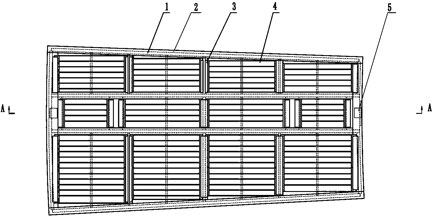
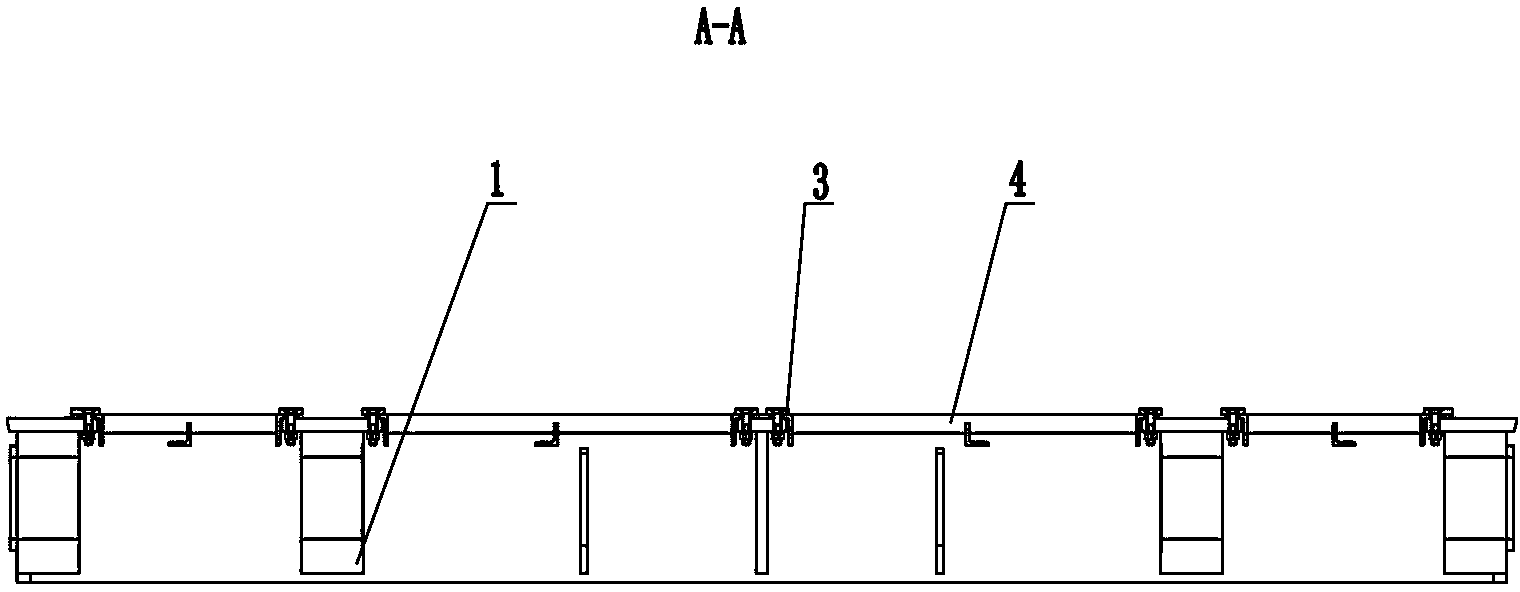
[0024] Such as figure 1 As shown, a trolley for a sintered annular cooler of the present invention includes a group of body trolleys arranged in sequence along the circumferential direction of the annular cooler, and is characterized in that the split trolley includes two eccentric trunnions 5 The fan-shaped trolley body 1 connected to the rotary frame of the annular cooler, the panel 2 provided on the fan-shaped trolley body, a set of grate plates 4 connected to the panel through a set of pressure plates 3,

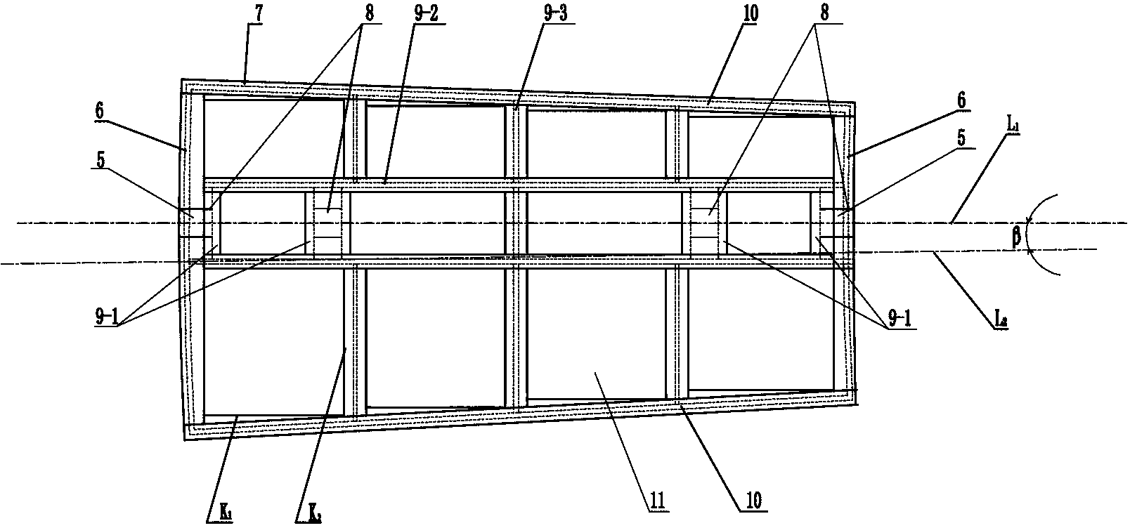
[0025] Such as figure 2 , 3 , 6, the fan-shaped trolley body 1 is a fan-shaped column frame structure with a cross-section surrounded by two arc-shaped vertical plates 6 and two plane vertical plates 10, and the inside of this frame structure is surrounded by a group of transverse ribs 9-2 and a group of longitudinal rein...


PUM


Abstract

The invention belongs to the technical field of metallurgical equipment and particularly relates to a sintering annular cooler pallet which comprises a set of separated type pallets which are sequentially arrayed in the circumferential direction of an annular cooler. The sintering annular cooler pallet is characterized in that each separated type pallet comprises a fan-shaped pallet body, a panel and a set of grates, wherein the fan-shaped pallet body is connected with a revolving frame of the annular cooler through two eccentric gudgeons,, the panel is arranged on a fan-shaped pallet body frame and the set of grates are connected with the panel through a set of pressing plates. According to the sintering annular cooler pallet, the structural defects of an original sintering annular cooler pallet are overcome. The pallet bodies are fan-shaped pallet bodies with eccentric shafts. An original triangle beam structure is cancelled and the ventilation area of the annular cooler is increased so that a sinter can be cooled more fully and sealing can be easier to achieve. In addition, the grates of the pallet are assembly type blind window grates. Therefore, when the pallet grates are damaged, the pallet does not need to be replaced integrally. Manpower and material resources are saved, and cost is saved.

Description

technical field [0001] The invention belongs to the technical field of metallurgical equipment, in particular to a trolley for a sintering ring cooler. Background technique [0002] The sintering ring cooler is one of the important equipment in the sintering production process, which is used to cool the hot sinter. The trolley is one of the important parts of the sintering ring cooler, which is used to carry hot sinter. The traditional sintered ring cooler has a number of trolleys with different numbers and the same shape according to the scale. The structure is similar to that of a ring. Each trolley is connected to the corresponding triangular beam on the rotary body through a spherical joint, and rotates around the rotary center of the ring cooler with the rotary body. The upper surface of the trolley carries hot pellets and is opened with a A series of regularly arranged ventilation holes, the lower part is ventilated with air at normal temperature, the cold air exchan...

Claims


Application Information

Patent Timeline
Patent Type & Authority Applications(China)
IPC IPC(8): F27B21/08F27D15/02
Inventor 王晶萍张忠波施荣陈沙沙曹静
Owner MCC NORTH (DALIAN) ENG TECH CO LTD
Why Eureka
Try Eureka