Conjugate cam jacquard shedding device

A technology of conjugate cam and jacquard opening, which is applied in the fields of jacquard machines, textiles, textiles and papermaking, etc., can solve problems affecting the accuracy of reciprocating motion, complex structure design of swing parts, and irregular loads, so as to avoid structural design defects and facilitate Effects of reduced assembly, maintenance, and repair workload

Inactive Publication Date: 2016-04-13
张军波
View PDF9 Cites 6 Cited by
  • Summary
  • Abstract
  • Description
  • Claims
  • Application Information

AI Technical Summary

Problems solved by technology

[0003] 1. Since the concentric pendulum tube 50 and the central pendulum shaft 60 have a "shaft-in-shaft kit" structure, the double-rotor rocker 31 and the double-rotor rocker 41 are located at the same upper position of the cam shaft 20, and the structural design of all the pendulum parts is complicated , the processing technology is complicated, and the manufacturing cost is high. As long as a certain part of the whole swing mechanism needs to be repaired, the whole set of swing mechanism needs to be assembled as a whole, and the maintenance is difficult and the workload is huge;
[0004] 2. The design structure of "shaft center shaft" makes the two sets of double-rotor rockers 31 and 41 can only be arranged in a cantilever beam type, which not only causes a large load on the "bearing" supporting the concentric swing shaft tube 50, but also exposes the The following operational defects: the rollers 410 installed at both ends of the double-rotor rocker 41 are in poor meshing state with the periphery of the outer conjugate cam set 40, and the meshing stability is poor, resulting in irregular loads on the periphery of the outer conjugate cam set 40. Similarly, The roller 310 (the other roller cannot be seen) installed on the double-rotor rocker 31 is in poor meshing state with the periphery of the inner conjugate cam set 30, and the meshing stability is poor, resulting in irregular loads on the periphery of the inner conjugate cam set 30;
[0005] 3. Since the bearings supporting the central pendulum shaft 60 are installed on the steps provided on the inner wall of the concentric pendulum shaft tube 50, the high loads formed by the jacquard openings are ultimately all supported by the "bearings" on both sides of the concentric pendulum shaft tube 50, The high load-bearing capacity conditions make the selection of bearings extremely demanding, but the "bearing" is still a vulnerable part of failure, and the workload of replacement and maintenance of the "bearing" is quite huge;
[0006] 4. Restricted by the "shaft center axis" structure: the swing arms 61, 62 and 63, 64 on the left and right sides of the central swing shaft 60 can only be designed in splits, that is, the two parts of the left split design: single Head swing arms 63, 64, and two parts designed separately on the right side: single-head swing arms 61, 62, if the overall design is such that each side is a single double-head swing arm, it cannot be assembled;
[0007] 5. Because the swing arms installed on each side of the central swing shaft 60 can only adopt the single-head swing arm with split design, the unfavorable factors are: the single-head swing arm processing parts have poor consistency during mass production, and the two The assembly accuracy of the four single-head swing arm assemblies on the side is difficult to meet the process design requirements, which affects the transmission of the movement from the central swing shaft 60, the four single-head swing arms on both sides, and the two-side tool holders 12 and 12' to the second set of knife lifting groups 11. The reciprocating motion accuracy of 11' will ultimately affect the shed forming accuracy

Method used


Image

  • Conjugate cam jacquard shedding device
  • Conjugate cam jacquard shedding device
  • Conjugate cam jacquard shedding device

Examples


Embodiment Construction

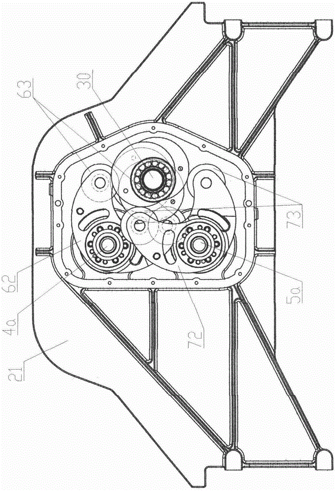
[0030] see figure 1 , 2 , 3, 4, 5, 6, 7, and 8 are preferred embodiments of the present invention.

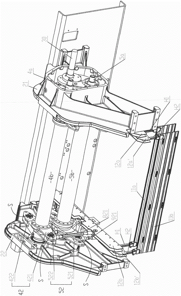
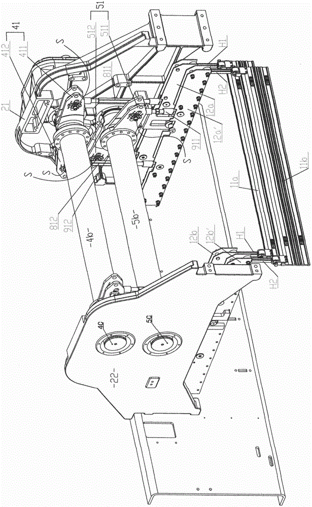
[0031] Such as figure 1 , 2 Shown, known knife lifting mechanism comprises two groups of lifting knives, two pairs of knife rests and some suspenders. Its left and right ends of the lifting knife group 11a when it is at the top dead center position are suspended and connected to a pair of knife rests made up of knife rests 12a, 12b through several suspension rods H1, and the lifting knife group 11a when it is at the bottom dead center position The left and right ends of the knife set 11b are suspended and connected to a pair of knife rests consisting of knife rests 12a' and 12b' through a number of suspension rods H2.

[0032] Both the knife lifting group 11a and the knife lifting group 11b are arranged longitudinally and spaced between the box-type side wall panels 21 and the plate-type side wall panels 22 by a number of equal-length lifting knives. The lifting knives i...


PUM


Abstract

The invention discloses a conjugate cam jacquard shedding device, and belongs to the technical field of jacquard loom shedding. The conjugate cam jacquard shedding device comprises two swinging mechanisms, a cam rotating shaft, an inner conjugate cam set and an outer conjugate cam set. The swinging mechanisms comprise an upper swinging shaft, a lower swinging shaft, a linkage upper swinging shaft, a linkage lower swinging shaft, an upper swinging shaft tube and a lower swinging shaft tube, wherein the upper swinging shaft and the lower swinging shaft are supported by bearings on a box-type side wall board and bearings on a box cover, the linkage upper swinging shaft and the linkage lower swinging shaft are supported by bearings on a plate-type side wall board, the upper swinging shaft and the linkage upper swinging shaft are in rigid connection through the upper swinging shaft tube, the lower swinging shaft and the linkage lower swinging shaft are in rigid connection through the lower swinging shaft tube, and the upper swinging shaft and the lower swinging shaft right facing the upper swinging shaft are located on the same side of the cam rotating shaft in the manner that the upper swinging shaft and the lower swinging shaft are arranged at an upper position and a lower position relative to the cam rotating shaft. The inner conjugate cam set and the outer conjugate cam set are in closure transmission connection with birotor rocking bars rigidly arranged on the upper swinging shaft and the lower swinging shaft respectively so as to control the upper swinging shaft and the lower swinging shaft to swing reversely in an equal-amplitude mode. Two pairs of tool rests are hinged to a double-end upper swinging arm, a double-end lower swinging arm, a linkage double-end upper swinging arm and a linkage double-end lower swinging arm through vertical connecting bars, wherein the double-end upper swinging arm and the double-end lower swinging arm are rigidly fixed to the upper swinging shaft and the lower swinging shaft and are single parts, and the linkage double-end upper swinging arm and the linkage double-end lower swinging arm are linked with the upper swinging shaft and the lower swinging shaft and are single parts. The device is reliable in operation, high in transmission precision and easy to assemble and maintain.

Description

【Technical field】 [0001] The invention relates to a conjugate cam jacquard shedding device, which is used for high-speed jacquard weaving shed formation and belongs to the technical field of jacquard machine shedding. 【Background technique】 [0002] The existing conjugate cam jacquard shedding device such as Figure 9 As shown, it is a central axis structure formed by a concentric swing tube 50 nested with a center swing shaft 60. The inner and outer sets of conjugate cam sets 30, 40 equipped on the cam rotary shaft 20 pass through the respective double rotor rockers 31. , 41 controls the concentric swing shaft tube 50 to swing back and forth oppositely with the center swing shaft 60, and the double-headed swing arms 51, 52 that are all installed on both sides of the concentric swing shaft tube 50 pass through the vertical connecting rods 71, 72 (the two vertical connecting rods on the left side are invisible ) control the front part of the corresponding knife rest 12' and t...

Claims


Application Information

Patent Timeline
Patent Type & Authority Applications(China)
IPC IPC(8): D03C3/36
CPCD03C3/36
Inventor 张军波马建明
Owner 张军波
Why Eureka
Try Eureka