Eureka AIR delivers breakthrough ideas for toughest innovation challenges, trusted by R&D personnel around the world.

Axial gap rotating electrical machine

A technology of axial gap and rotating motor, which is applied to synchronous motors with stationary armatures and rotating magnets, electrical components, electromechanical devices, etc., can solve the problems of improving and not being able to benefit the performance of rotating motors, and reduce manufacturing costs. The effect of reducing the number of assembly steps and improving assembly accuracy

Active Publication Date: 2012-03-21
PROTERIAL LTD
View PDF8 Cites 9 Cited by
  • Summary
  • Abstract
  • Description
  • Claims
  • Application Information

AI Technical Summary

Problems solved by technology

[0013] In short, in the structure of the rotating electric machine of the above patent document, when assembling the rotating electric machine, there are problems in high-precision positioning of the stator core and simplification of the manufacturing process, and as a result, it cannot contribute to the improvement of the performance of the rotating electric machine as a final product

Method used


Image

  • Axial gap rotating electrical machine
  • Axial gap rotating electrical machine
  • Axial gap rotating electrical machine

Examples


Embodiment Construction

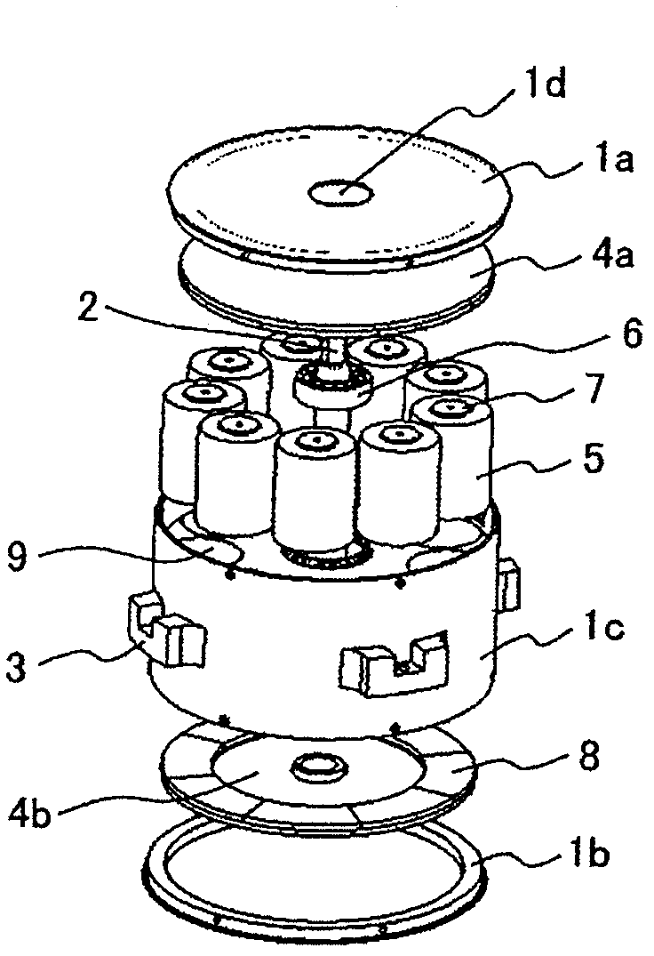
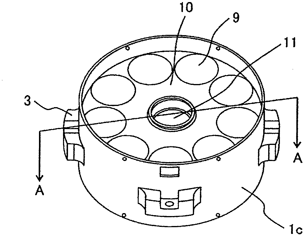
[0068] Hereinafter, embodiments of the present invention will be described using the drawings. Here, an axial gap motor will be described as an example of the axial gap type rotating electric machine of the present invention, but the structure described below can also be used as a generator instead of a motor.

[0069] 【Example】

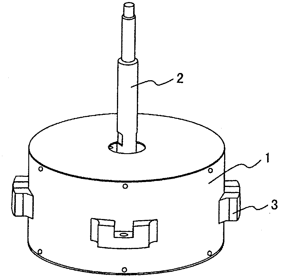
[0070] figure 2 It is a diagram showing the external shape of a general axial gap type rotating electrical machine, and has a shaft 2 extending upward in the center of a substantially cylindrical rotating electrical machine case 1 made of a non-magnetic material. The shaft 2 can be taken out from both sides of the casing 1 of the electric rotating machine, and an example of taking out only one side is shown here.

[0071] It should be noted that the rotating electrical machine housing 1 is provided with a mounting portion 3 for fixing the rotating electrical machine. In addition, as for the material of the case 1, when it is applied to a motor, i...


PUM


Abstract

When an axial gap rotating electrical machine is assembled, stator cores are accurately positioned and a manufacturing process therefor is simplified. The axial gap rotating electrical machine is comprised of: a housing frame body having a first space in the cylindrical central part thereof and multiple second spaces located in the circumferential direction which have the same distances from the center; a shaft rotatably provided in the first space in the housing frame body; a core placed in each of the second spaces in the housing frame body and a coil arranged outside of the core; a rotor yoke fixed on the shaft, extended in the direction of the circumference thereof, and having multiple magnets arranged in circumferential positions confront the cores; and a case having a hole for the shaft and housing the housing frame body and the rotor yoke.

Description

technical field [0001] The present invention relates to an axial gap type rotating electric machine. Background technique [0002] In general, an axial gap type rotating electrical machine includes: a rotating member with permanent magnets on the opposing surfaces of the two discs, and a shaft connecting the two discs at the center of the disc; , which is composed of a plurality of iron cores and coils facing each other with a permanent magnet separated by a gap; a pair of freely rotatable bearings supported at both ends of the shaft; and a bearing seat that holds the pair of bearings. [0003] In this way, Patent Document 1 describes, for example, an axial gap type rotating electrical machine in which a rotor and a stator are arranged to face each other in the central axis direction. [0004] With regard to this axial gap type rotating electrical machine, the wound independent electromagnetic steel sheet core and the coil are arranged so as to be positioned in the circumfe...

Claims


Application Information

Patent Timeline
Patent Type & Authority Applications(China)
IPC IPC(8): H02K21/24H02K1/02
CPCH02K21/24H02K1/14H02K1/182
Inventor 王卓男榎本裕治伊藤元哉正木良三板桥弘光黄柏英
Owner PROTERIAL LTD
Why Eureka
Eureka Blog
Learn More