Device for creating a reactionable flowable compound

A mixture, reactive technology, applied in the direction of fluid mixer, mixer, mechanical equipment, etc., can solve the problems of production downtime, time-consuming, high cost, cleaning operation, etc.

Inactive Publication Date: 2009-04-01
SULZER CHEMTECH AG
View PDF2 Cites 0 Cited by
  • Summary
  • Abstract
  • Description
  • Claims
  • Application Information

AI Technical Summary

Problems solved by technology

Effects range from production downtime, production scrap, time-consuming and / or costly cleaning operations, to replacement of damaged machine parts

Method used


Image

  • Device for creating a reactionable flowable compound
  • Device for creating a reactionable flowable compound
  • Device for creating a reactionable flowable compound

Examples


Embodiment Construction

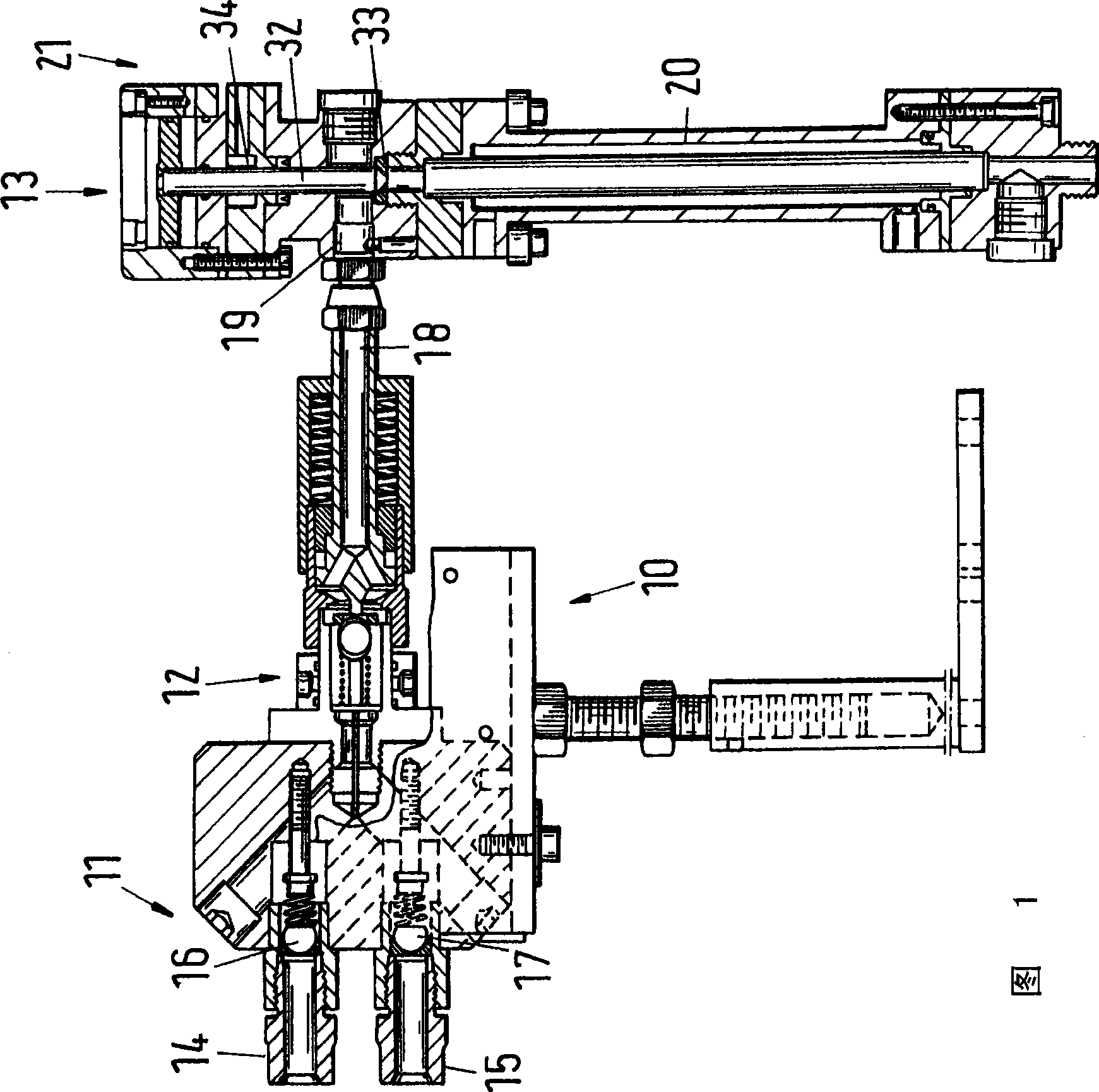
[0018] FIG. 1 shows a device 10 for delivering reactive flowable mixtures according to the prior art. The apparatus comprises a supply device 11 , a collection arrangement 12 and a mixing device 13 . The supply means comprise a first supply line 14 for the first component 3 and a second supply line 15 for the second component 5 . The first supply line contains a first non-return valve 16 and the second supply line 15 contains a second non-return valve 17 . Both components lead together into a collection device 12 downstream of the non-return valves 16 , 17 . Both components leave the collection device 12 through the collection channel 18 . Collection channel 18 contains the first and second components. Hardly any mixing of the components takes place as they pass through the collection channel 18 if they are high viscosity fluids. The collecting channel 18 leads to the actual mixing device 13 , in which an inlet channel 19 is arranged which leads to a mixing channel 20 whic...


PUM


Abstract

The invention relates to a device for the production of a reactive flowable mixture, including a mixing block (1) which includes at least one first passage (2) and second passage (4) for at least one first component (3) of the mixture and a collection passage (7) for the mixture (6). The first and second passages are communicated to the collection passage (7) which comprises at least one mixing mechanism (36).

Description

technical field [0001] The present invention relates to apparatus for producing reactive flowable mixtures. Background technique [0002] Devices of this type are intended in particular for use in the method described in EP-A-1600470. The described method is used in particular for the processing of silicone rubber (or LSR—"Liquid Silicone Rubber"). Silicone rubber is supplied in two components. The two components are not reactive separately and can be stored at room temperature. Only through the mixture of the individual components is a reactive mixture produced, the reaction time of which depends on the composition of the mixture and on additives such as catalysts and inhibitors and can be adjusted within wide limits. The processing equipment in which the reaction takes place is followed by mixing equipment. Molded parts are produced in processing equipment using continuous or discontinuous processes. Such continuous processes are eg extrusion; especially pressure form...

Claims


Application Information

Patent Timeline
IPC IPC(8): B29B7/02B29B7/22B29C44/34
CPCB29B7/325B29B7/7457B01F5/0619B01F2015/0221F16L23/032B01F5/0473F16L41/086B29B7/823B29B7/801B29B7/7605B29B7/7636B29B7/7647B29B7/7657B29B7/826B01F25/3141B01F25/43161B01F35/715B29B7/34B29B7/80
Inventor J·斯图德莱克S·卢蒂格A·万兹基S·哈比比-奈尼
Owner SULZER CHEMTECH AG
Why Eureka
Try Eureka