Method for preventing pressure peaks in a working medium cycle having a hydrodynamic machine

A working medium, hydraulic machine technology, applied in the direction of hydraulic brakes, hydraulic resistance brakes, mechanical equipment, etc., can solve problems such as equipment and control inconvenience

Inactive Publication Date: 2012-03-21
VOITH PATENT GMBH
View PDF1 Cites 3 Cited by
  • Summary
  • Abstract
  • Description
  • Claims
  • Application Information

AI Technical Summary

Problems solved by technology

However, requiring additional equipment and controls is less convenient

Method used


Image

  • Method for preventing pressure peaks in a working medium cycle having a hydrodynamic machine
  • Method for preventing pressure peaks in a working medium cycle having a hydrodynamic machine
  • Method for preventing pressure peaks in a working medium cycle having a hydrodynamic machine

Examples


Embodiment Construction

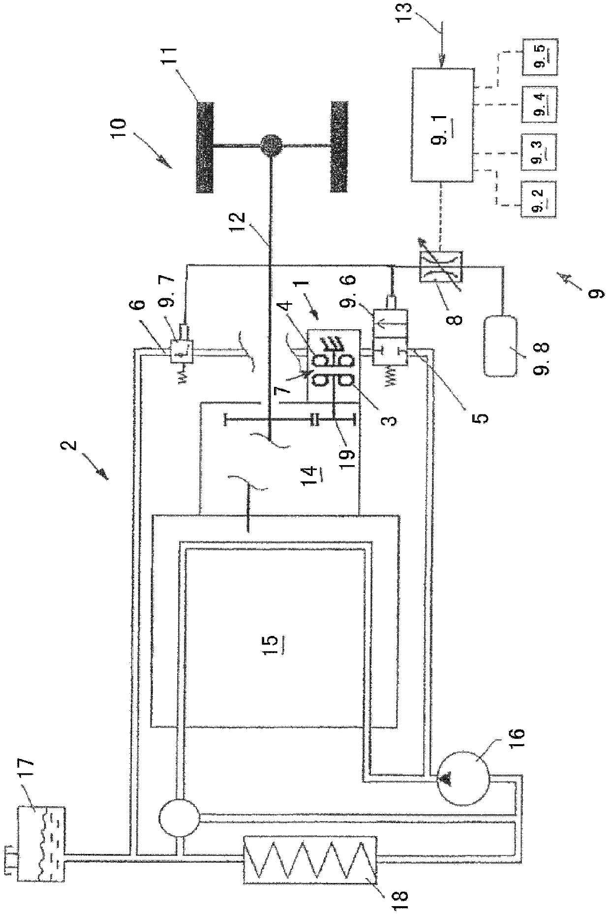
[0023] figure 1 A drive train 10 of a motor vehicle with an external working medium circuit 2 is shown. In this case, the working medium circuit 2 represents the cooling circuit. Furthermore, the hydraulic machine 1 , in this case a hydraulic retarder, is arranged in the external working medium circuit 2 , the retarder being arranged in this case as a water stop, so that its working medium also represents the vehicle at the same time. The cooling medium of the cooling circuit.

[0024] From the flow direction of the fluid, the following components are arranged in the working medium circuit 2 after the retarder: valve 9.7, hole for compensating adjustment tank 17, heat exchanger 18, circulation pump 16 and another valve 9.6. In this case, the valve 9 . 7 is arranged in the working medium circuit 2 in the region of the working medium outlet 6 and the valve 9 . 6 is arranged in the working medium circuit 2 in the region of the working medium inlet 5 . The internal combustion e...


PUM


Abstract

The invention relates to a method for preventing pressure peaks in a working medium cycle in which a hydrodynamic machine is operated, wherein the hydrodynamic machine comprises a primary wheel and a secondary wheel which together form a toroidal working chamber that can be filled and emptied via a working medium inlet and working medium outlet in order to hydrodynamically transmit torque from the primary wheel to the secondary wheel. The invention is characterized in that the rate of change of the flow cross-section for the working medium that flows into and / or out of the working chamber is changed depending on a predetermined input variable when connecting and disconnecting the hydrodynamic machine.

Description

technical field [0001] The invention relates to a method for preventing pressure peaks in a working medium circuit caused by the operation of a hydraulic machine. Background technique [0002] The hydrodynamic machine includes a working chamber filled with a working medium in order to transmit the respective torque of the drive energy from the main wheel of the hydrodynamic machine to the secondary wheel. [0003] Such hydraulic machines configured as hydraulic converters or hydraulic couplings are known to those skilled in the art. They are used in particular in the drive train of a motor vehicle in order to hydrodynamically transmit drive energy from the drive engine of the motor vehicle to the drive wheels or another unit. Such a hydrodynamic machine can also be arranged as a retarder, in which case the secondary wheel is arranged in a fixed manner, or the secondary wheel rotates in a rotational manner in the opposite direction to the main wheel. This allows deceleratio...

Claims


Application Information

Patent Timeline
Patent Type & Authority Applications(China)
IPC IPC(8): B60T10/02
CPCB60T10/02F16D57/06
Inventor 迪特尔·劳基曼约根·贝兹托马斯·杰尔
Owner VOITH PATENT GMBH
Why Eureka
Try Eureka