Iron-core shielding roller type electromagnetic stirring sensor

An electromagnetic stirring and inductor technology, applied in the field of electromagnetic stirrers, can solve the problems of reducing the ampere-turns and magnetic permeability area of ​​a roller electromagnetic stirring device, low efficiency of active magnetic field, reducing electromagnetic stirring force, etc., so as to solve the electromagnetic stirring force Insufficiency and inefficiency, solving low magnetic field efficiency, increasing the effect of electromagnetic stirring force

Active Publication Date: 2012-03-28
HUNAN KEMEIDA ELECTRIC
View PDF5 Cites 2 Cited by
  • Summary
  • Abstract
  • Description
  • Claims
  • Application Information

AI Technical Summary

Problems solved by technology

But the existing roller-type electromagnetic stirring device has the following defects and deficiencies: 1. The magnetic shielding ring is set on the outer layer of the coil winding. Because of the thickness of the magnetic shielding layer outside the coil, this will inevitably occur in the same space (compared with no shielding layer). It is necessary to greatly reduce the cross-sectional area of ​​the coil winding and the iron core, that is, greatly reduce the number of ampere turns and the magnetic conduction area of ​​the roller electromagnetic stirring device, and also reduce the electromagnetic stirring force; 2. The roller electromagnetic stirring device without shielding layer Stirring device, the magnetic field is evenly distributed along the radial direction of the iron core, the magnetic flux leakage is large, the working magnetic field is small, the proportion of useful work is small, and the energy consumption is also inefficient
3. The coil is full-wound cylindrical iron core. The coil is equivalent to the magnetic shielding layer. While improving the utilization rate of the winding space, it shields a part of the effective working magnetic field, making it enclosed in the core and causing loss, and the efficiency of the active magnetic field is low.

Method used


Image

  • Iron-core shielding roller type electromagnetic stirring sensor
  • Iron-core shielding roller type electromagnetic stirring sensor
  • Iron-core shielding roller type electromagnetic stirring sensor

Examples


Embodiment Construction

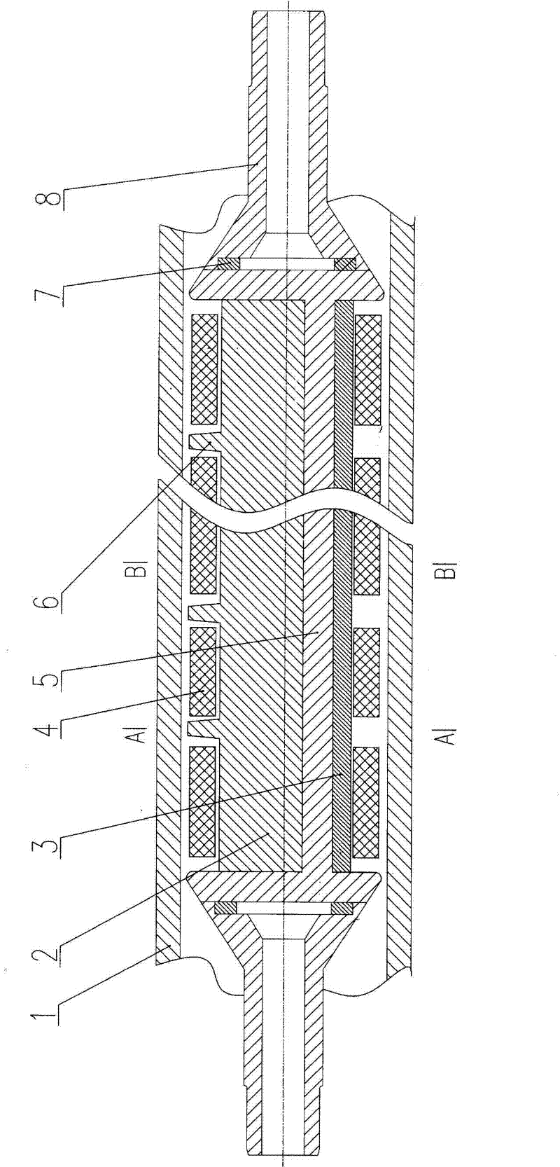
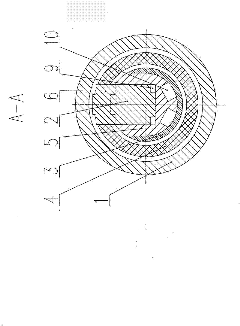
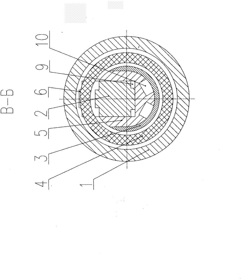
[0012] Depend on Figures 1 to 3 It can be seen that the present invention includes an iron core and a coil winding, wherein:

[0013] The iron core is a combined iron core, and the outer surface of the combined iron core is wound with a coil winding 4 in segmental gaps. The combined iron core and the coil winding 4 are arranged in the hollow roller 1 with gaps, and are fixed by the iron core shaft ends 8 provided at both ends. Combined iron core and coil winding 4 and hollow roller 1 rotate relative to each other;

[0014] The combined iron core includes an iron core composed of a main iron core 2 and a secondary iron core 5, a U-shaped shielding ring 3 wrapped around the outside of the secondary iron core 5 and the inside of the coil winding 4, and a shielding ring 3 arranged on the iron core and the coil winding 4 O-shaped shielding rings 7 at both ends, wherein the magnetic poles 6 are arranged between the coil windings 4 wound on the main core 2.

[0015] The U-shaped s...


PUM


Abstract

The invention relates to an iron-core shielding roller type electromagnetic stirring sensor, which comprises an iron core and coil windings, wherein the iron core is a combined iron core, the coil windings are wound around the outer circumference of the combined iron core in sections at intervals, the intervals between the combined iron core and the coil windings are arranged in a hollow roller, the combined iron core and the coil windings are fixed by iron core shaft ends at two ends, and the combined iron core, the coil windings and the hollow roller correspondingly rotate to move; the combined iron core comprises the iron core, U-shaped shielding rings and O-shaped shielding rings, the iron core consists a main iron core and a secondary iron core, the U-shaped shielding rings annularlycover the outer side of the secondary iron core and the inner side of each coil winding, and the O-shaped shielding rings are arranged at two ends of the iron core and the coil windings, wherein magnetic poles are arranged among all coil winding groups wound on the main iron core. The invention has the advantages of improving the effect of a roller type electromagnetic stirring device and increasing the magnetic conduction area of the iron core, the strength of a magnetic field and the electromagnetic stirring force, and also solves the problems that the stirring force is not enough, the effect is low, the efficiency is low, the electromagnetic stirring force is small, the magnetic leakage of a nonworking area is large.

Description

technical field [0001] The invention relates to an electromagnetic stirrer in the technical field of metallurgical slab continuous casting process equipment, in particular to an iron core shielding roller type electromagnetic stirring inductor. Background technique [0002] At present, there are various slab S-EMS structures, mainly including: box type electromagnetic stirring device, magnetic pole insertion type electromagnetic stirring device and roller type electromagnetic stirring device. The roller electromagnetic stirring device has a special structure. It uses a specially designed and compact electromagnetic induction coil (traveling wave magnetic field sensor) installed in a hollow roller (similar to the supporting guide roller of the slab continuous casting machine) to The liquid core inside the billet shell is electromagnetically stirred. In recent years, the roller electromagnetic stirring device is more and more used in the slab S-EMS because of its convenient i...

Claims


Application Information

Patent Timeline
Patent Type & Authority Applications(China)
IPC IPC(8): B22D11/115
Inventor 郑勇乔志洪侯亚雄彭立新赵训迪
Owner HUNAN KEMEIDA ELECTRIC
Why Eureka
Try Eureka