Constant-flow feeding device

A feeding device and steady flow technology, applied in the field of wet material feeding equipment, can solve the problems of unguaranteed batching accuracy, sticking on the material wall, and harsh working environment, etc., to achieve enhanced wear resistance, smooth material flow, The effect of reducing labor intensity

Inactive Publication Date: 2012-03-28
NORTHERN ENG & TECH CORP MCC
View PDF6 Cites 1 Cited by
  • Summary
  • Abstract
  • Description
  • Claims
  • Application Information

AI Technical Summary

Problems solved by technology

[0002] In actual production, the lower part of the cone section of the metal ore trough in the silo is directly connected to the feeding equipment. Since there is no vibration buffering process in the middle, when the feeding equipment is unloading slowly, wet materials, iron materials with high moisture content, and fuel are in the feeder. The lower part of the cone section of the bin metal ore trough is frequently blocked, affecting the feeding, and at the same time, arching occurs, resulting in unsmooth material flow. On the other hand, due to unsmooth feeding, the material gradually sticks to the material wall
Due to the large volume and deep position of the silo, when the material is blocked in the cone section of the metal ore tank of the silo, the post workers need to go down to the silo to clean it up. The working environment is harsh, the labor intensity is high, and the processing time is long. Due to the unstable material flow, the batching accuracy cannot be guaranteed, which seriously affects the production

Method used


Image

  • Constant-flow feeding device
  • Constant-flow feeding device
  • Constant-flow feeding device

Examples


Embodiment Construction

[0023] The specific embodiments of the present invention are described below in conjunction with the drawings.

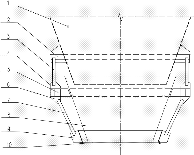
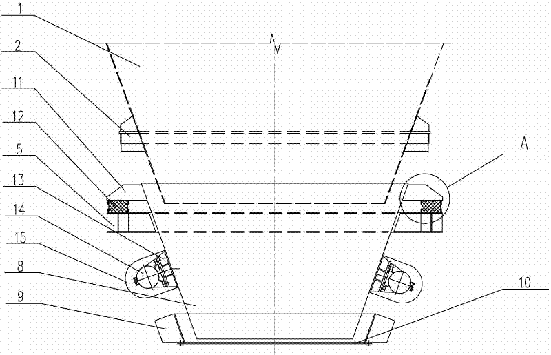
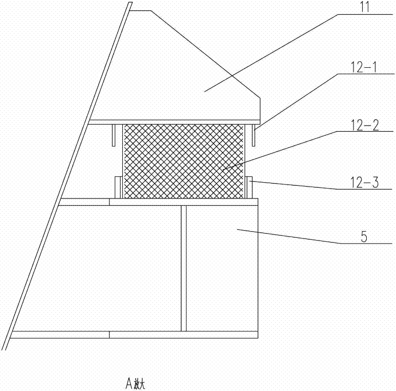
[0024] Such as figure 1 , figure 2 , image 3 As shown, the steady flow feeding device of the present invention is characterized in that it includes a consolidation ring 2 fixedly connected to the silo metal ore trough 1, and the consolidation ring carries the load of the entire device. The hopper body 8 is set under the silo metal ore tank 1. The bottom of the silo metal ore tank 1 is inserted into the hopper body 8. The dihedral angle between the generatrix of the hopper body 8 and the plane where the lower mouth is located is greater than or equal to 70 degrees, This angle is conducive to the downward movement of materials. The inner surface of the funnel body 8 is provided with a rare earth oil-containing nylon liner to enhance its wear resistance and prolong its service life. A set of ear seats 11 evenly arranged on the outer surface of the upper part of the fu...


PUM


Abstract

The invention relates to a constant-flow feeding device which is characterized by comprising a concreted ring fixedly connected with a bunker metallic ore chute, a hopper body arranged below the bunker metallic ore chute, a group of lugs uniformly arranged on the outer surface of the upper part of the hopper body, a backing ring arranged below the group of lugs, buffering mechanisms respectively arranged between the upper surface of the backing ring and the lugs, a group of upper connecting plates which are uniformly arranged on the upper surface of the backing ring and crossly arranged together with the buffering mechanisms, a group of upper connecting rods respectively connected with the upper connecting plates and the concreted ring, a group of lower connecting plates uniformly arranged on the lower surface of the backing ring, an annular flange arranged below the hopper body, a circumferential protective plate arranged on the upper surface of the annular flange, a lower connecting rod for connecting the circumferential protective plate with the lower connecting plates, and a group of vibration mechanisms respectively arranged at outer surfaces at two sides in the middle of the hopper body, wherein the bottom of the bunker metallic ore chute is inserted into the hopper body; and the annular flange is connected with a feeding apparatus through a bolt. The constant-flow feeding device has the advantages that the discharge is smooth, the material flow is stable and uniform, and the overhauling is convenient.

Description

Technical field [0001] The invention relates to the technical field of wet material feeding equipment, in particular to a steady flow feeding device. Background technique [0002] In actual production, the lower part of the cone of the metal ore trough of the silo is directly connected to the feeding equipment. Because there is no vibration buffering process in the middle, when the feeding equipment is slow to discharge, the wet materials and the iron and fuel with large moisture are in the material. The lower part of the cone section of the silo metal ore trough is frequently blocked and affects the cutting, and at the same time, the arching phenomenon occurs, which causes the material flow to be unsmooth. On the other hand, due to the unsuccessful cutting, the material gradually adheres to the material wall. Due to the large volume of the silo and the deep silo, when the material is blocked in the cone section of the silo's metal ore trough, the post workers need to go down...

Claims


Application Information

Patent Timeline
Patent Type & Authority Applications(China)
IPC IPC(8): B65D88/66
Inventor 王明侠朱占军
Owner NORTHERN ENG & TECH CORP MCC
Why Eureka
Try Eureka