Automatic correcting error control on converter tilting angle

A technology of automatic deviation correction and control method, applied in the direction of manufacturing converters, etc., can solve the problems of angle error, encoder deviation, debugging difficulties, etc., to achieve the effect of eliminating deviation

Inactive Publication Date: 2013-10-30
WISDRI ENG & RES INC LTD
View PDF4 Cites 1 Cited by
  • Summary
  • Abstract
  • Description
  • Claims
  • Application Information

AI Technical Summary

Problems solved by technology

[0003] 1. Due to the product characteristics of the master controller, it is very difficult to debug the two master control points at 0 degrees of the converter into a sharp signal. In this way, it will inevitably cause the converter angle displayed in an angle area are all 0 degrees
[0004] 2. Because the encoder of the converter may deviate during the rotation process, there may still be angle errors in non-0-degree areas such as the tapping hole, and this angle error will have a great impact on production

Method used


Image

  • Automatic correcting error control on converter tilting angle

Examples


Embodiment Construction

[0018] The technical solutions of the present invention will be further described below in conjunction with the accompanying drawings and specific embodiments.

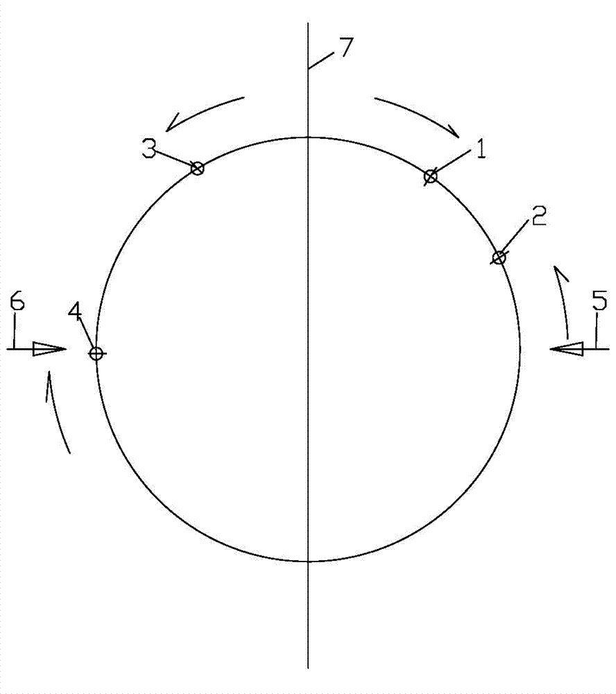
[0019] The automatic deviation correction control method of the converter tilting angle involved in the present invention includes PLC control, a rotary encoder and a master controller, the master controller is provided with 4 master controller control points, the first master controller Control point 1 is set in the area of ​​0~30 degrees when the converter rotates clockwise to the front of the furnace, the control point 2 of the second master controller is set in the area of ​​50~30 degrees when the converter rotates counterclockwise to the back of the furnace, and the third master controller Let the control point 3 of the controller be set in the area of ​​360~340 degrees after turning counterclockwise to the back of the furnace, and the control point 4 of the fourth main controller is set in the area of ​​270~300 d...


PUM


Abstract

The invention relates to automatic correcting error control on converter tilting angle. Included is a PLC (Programmable Logic Controller) control, a rotary encoder and a master controller. The master controller is provide with four master controller control points; a first master controller control point is arranged in an area, which forms by the converter rotating clockwise 0-30 DEG towards a direction in front of the furnace; a second master controller control point is arranged in an area, which forms by the converter rotating 30-50 DEG anticlockwise towards a direction behind the furnace; a third master controller control point is arranged in an area, which forms by the converter rotating 340-360 DEG anticlockwise towards a direction behind the furnace; and a fourth master controller control point is arranged in an area, which forms by the converter rotating 270-300 DEG clockwise from furnace back to front. According to a technical scheme of the invention, control point can be arranged easily near each master controller control point angle, and are corrected by signal level and a rotary encoder of each master controller control point to eliminate deviation, so as to ensure needs of production technology and omit subsequent maintenance after debug.

Description

technical field [0001] The invention relates to a steelmaking converter process equipment in the metallurgical industry, in particular to an automatic deviation correction control method for a converter tilting angle. Background technique [0002] The tilting angle control of the converter is generally calculated by the PLC according to the pulse number of the encoder, and two control points of the master controller are set at 0 degrees of the converter. When the signals of the two master controllers are both 1 or 0, the converter is displayed. 0 degrees, according to which to check the converter angle calculated by the encoder. This control method has the following disadvantages: [0003] 1. Due to the product characteristics of the master controller, it is very difficult to debug the two master control points at 0 degrees of the converter into a sharp signal. In this way, it will inevitably cause the converter angle displayed in an angle area It's all 0 degrees. [0004...

Claims


Application Information

Patent Timeline
Patent Type & Authority Patents(China)
IPC IPC(8): C21C5/50
Inventor 吉青
Owner WISDRI ENG & RES INC LTD
Why Eureka
Try Eureka