Supercharge Your Innovation With Domain-Expert AI Agents!

Throttling device

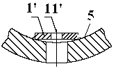
A technology of throttling device and throttling seat, which is applied in the direction of flange connection, pipe/pipe joint/pipe fitting, passing element, etc., can solve the problem that the throttling orifice 1' is easy to fall off, inconvenient to disassemble and replace, and the throttling function fails, etc. problems, to achieve the effect of enhancing the firmness and safety of the device, improving the installation accuracy, and avoiding wear and corrosion

Active Publication Date: 2013-08-21
SHANGHAI BOILER WORKS
View PDF7 Cites 0 Cited by
  • Summary
  • Abstract
  • Description
  • Claims
  • Application Information

AI Technical Summary

Problems solved by technology

The traditional throttling device has the following defects: First, because the traditional throttling device is directly welded to the inner wall of the water bag 5 under the water cooling wall, it is inconvenient to disassemble and replace
It is susceptible to serious wear and corrosion under water pressure, pickling and other working conditions, and the traditional throttling device is not well protected; moreover, because the throttling orifice 1' is flat, the inner wall of the water bag 5 under the water cooling wall is The circular arc surface, when the two are welded, the weld height is small, the weld quality is difficult to control, the throttle orifice 1' is easy to fall off, and the material of the throttle orifice 1' is often different from the material of the water bag 5 cylinder under the water cooling wall. Dissimilar material welding problems often occur during assembly and welding; at the same time, due to the large number of such throttling devices in actual engineering, they are similar in structure except for the area of ​​the orifice 11', so they are often used during installation. It is easy to install wrongly, and the phenomenon of mixed installation occurs; moreover, the size of the orifice 11' on the orifice plate 1' will be worn and enlarged with the operation of the unit for a certain period of time, thereby changing the original design flow rate of the working fluid Allocation
Due to these disadvantages, the throttling effect will fail, which will lead to deviations in the flow distribution of the working fluid, fail to achieve the design effect, and fail to ensure a reasonable mass flow rate of the working medium and a uniform inlet temperature of the water-cooled wall, which may cause the wall of the water-cooled wall to overheat. A tube burst occurred, causing the boiler to shut down and causing huge economic losses

Method used


Image

  • Throttling device
  • Throttling device
  • Throttling device

Examples


Embodiment Construction

[0033] The present invention will be further described below in combination with preferred embodiments, wherein the water bag 5 under the water wall of the boiler is taken as a specific embodiment of the pressure vessel 5 as an example.

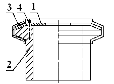
[0034] Such as Figure 4 and Figure 7 As shown, a throttle device includes a throttle orifice 1 , a throttle seat 2 , and a clamp ring 3 .

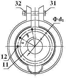
[0035] Throttle orifice 1 is provided with throttling holes 11 and N 1 A first pin hole 12, the orifice 11 is arranged in the center of the orifice plate 1, the diameter is Φd 1 , the first pin hole 12 is provided on the surface of the throttling orifice plate 1 and penetrates through the throttling orifice plate 1 .

[0036] Throttle seat 2 is a hollow column, such as Figure 2~Figure 4 As shown, the outer surface of the throttle seat 2 is smooth, and it is welded and connected with the water bag 5 under the water wall of the boiler. Its material is the same as that of the water bag 5 under the wat...


PUM


Abstract

A throttling device comprises a throttling perforated plate (1), a throttling seat (2), and a clamping ring (3). The throttling perforated plate (1) is connected to and fixed with the throttling seat (2) through a pin (4). The throttling perforated plate (1) is provided with a pin hole and a throttling hole (11). An alignment angle of the pin hole is corresponding to the diameter of the throttling hole (11), and alignment angles of different pin holes correspond to diameters of different throttling holes (11). The throttling seat (2) is welded to or screw-connected to a pressure vessel. The clamping ring (3) clamps the throttling perforated plate (1) and the throttling seat (2). The throttling device is durable, firm, and easy to install, and is capable of effectively avoiding mixed assembly of the throttling perforated plate (1), thereby improving the assembling accuracy of the throttling perforated plate (1).

Description

technical field [0001] The invention relates to a working fluid flow control device, in particular to a throttling device. Background technique [0002] The throttling device is widely used in the technical field of working medium distribution, and is used in various pressure vessels, especially mainly distributed in the water bag 5 under the water wall of the boiler. According to the results of hydrodynamic calculation, the flow rate of the working medium in the water wall tubes of different circuits is different at the outlet pipe system of the water wall 5 cylinder under the water wall. In the design, a throttling device should be set here to realize the control of the flow of working fluid in the water wall tubes of different circuits. The setting of the throttling device can ensure the rationality of the mass flow rate of the working medium, the uniformity of the inlet temperature of the water cooling wall, and at the same time ensure that the metal temperature of the ...

Claims


Application Information

Patent Timeline
Patent Type & Authority Patents(China)
IPC IPC(8): F16L55/027
CPCF16L23/006F16L55/02718
Inventor 王瑞娟周曙光赵沈慧
Owner SHANGHAI BOILER WORKS
Features
  • R&D
  • Intellectual Property
  • Life Sciences
  • Materials
  • Tech Scout
  • Unparalleled Data Quality
  • Higher Quality Content
  • 60% Fewer Hallucinations
Learn More