Alignment method for optical axis of compound wave plate and device for same

A composite wave plate and optical axis technology, which is applied in the field of the optical axis alignment method and device of the composite wave plate, can solve the problems such as the complex alignment process of the composite wave plate, and achieve the effect of high-precision alignment and wide application prospect.

Active Publication Date: 2012-03-28
HUAZHONG UNIV OF SCI & TECH
View PDF4 Cites 18 Cited by
  • Summary
  • Abstract
  • Description
  • Claims
  • Application Information

AI Technical Summary

Problems solved by technology

Although the alignment method proposed by Collins et al. has higher alignment accuracy than the traditional manual alignment method, the alignment process

Method used


Image

  • Alignment method for optical axis of compound wave plate and device for same
  • Alignment method for optical axis of compound wave plate and device for same
  • Alignment method for optical axis of compound wave plate and device for same

Examples


Embodiment Construction

[0023] The principle and working process of the method of the present invention will be described in further detail below in conjunction with the accompanying drawings and examples.

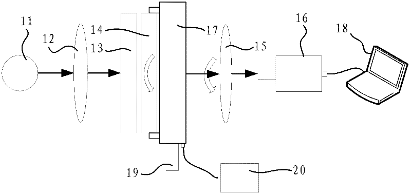
[0024] (1) Project linearly polarized light vertically onto a chip of the compound wave plate to be aligned, and exit vertically from another chip of the compound wave plate;

[0025] (2) The polarization state of linearly polarized light will change (from linearly polarized light to elliptically polarized light) after passing through the composite wave plate to be aligned. The transmitted light intensity signal received by the detector contains the actual phase delay information of the composite wave plate to be aligned;

[0026] (3) The actual phase delay δ of the composite wave plate to be aligned can be further obtained from the transmitted light intensity signal obtained in step (2);

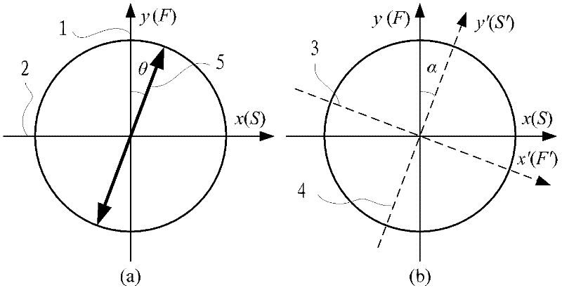
[0027] figure 1 is a schematic diagram when there is an alignment error α between the two wafers that mak...


PUM


Abstract

The present invention discloses an alignment method for the optical axis of a compound wave plate and a device for the same. Two wafers of a compound wave plate to be aligned are arranged on a bracket, and then are mounted on a fixed wave plate chuck and a rotary wave plate chuck respectively; light emitted from a light source forms linearly polarized light after passing through a polarizer; after passing through the compound wave plate to be aligned, the linearly polarized light become changed in the polarization state; according to the intensity signal of transmitted beam detected by a detector, the variation amplitude of the phase delay fluctuation quantity of the compound wave plate to be aligned can be obtained further; the relative magnitude of the variation amplitude of the phase delay fluctuation quantity is compared; and the rotary wave plate chuck is controlled to rotate through an electric control rotary table until the optical axis of the compound wave plate is aligned to be in the required precision range. The device comprises the light source, the polarizer, the fixed wave plate chuck, the rotary wave plate chuck, a rotary polarization analyzer, the detector, the electric control rotary table, a computer, a stepping motor and an electric control rotary table controller. The method can align the optical axis of a compound wave plate with high precision, the deviceis simply equipped, and the operation is simple.

Description

technical field [0001] The invention belongs to the field of design and manufacture of optical instrument components, and in particular relates to a method and device for aligning the optical axis of a composite wave plate, which is suitable for precise alignment and calibration of the optical axes of two or more wafers in the compound wave plate. Background technique [0002] Wave plate (also can be referred to as chip. In the present invention, we claim that the wave plate that is made up of two or more wafers is a compound wave plate, and the single wave plate that claims to form a compound wave plate is a chip, to show difference. In not When making a special distinction, the composite wave plate and the wafer are collectively referred to as the wave plate.) is an optical element commonly used in the field of optical instrument design and optical measurement, which can make the two perpendicular components of polarized light produce additional optical path difference (or ...

Claims


Application Information

Patent Timeline
IPC IPC(8): G02B7/00G02B27/28
Inventor 刘世元陈修国谷洪刚张传维
Owner HUAZHONG UNIV OF SCI & TECH
Why Eureka
Try Eureka