
Alternating current permanent magnet synchronous spindle motor for threading machine

A permanent magnet synchronous, spindle motor technology, applied in the direction of synchronous machine parts, etc., can solve the problems of affecting the working efficiency of tapping machines, complex structure and speed regulating mechanism, slow rotation of the rotating shaft, etc., to achieve easy promotion and use, wide range Effects of load adaptability and work efficiency improvement

Inactive Publication Date: 2012-03-28
XIAN HESHENG POWER TECH CO LTD
View PDF4 Cites 0 Cited by
  • Summary
  • Abstract
  • Description
  • Claims
  • Application Information

AI Technical Summary

Problems solved by technology

[0003] At present, for the electric tapping machine, its structure and speed regulating mechanism are relatively complicated, the rotational inertia of the rotating shaft is too large, and the rotation of the rotating shaft is correspondingly slow, which is easy to cause work failure and affect the working efficiency of the tapping machine. Work brings great inconvenience
Secondly, the belt drive is mostly used between the motor and the main shaft of the general tapping machine. When the load is too large in the tapping process, the belt is easy to slip, which will cause a large tapping error.

Method used


Image

  • Alternating current permanent magnet synchronous spindle motor for threading machine
  • Alternating current permanent magnet synchronous spindle motor for threading machine

Examples


Embodiment Construction

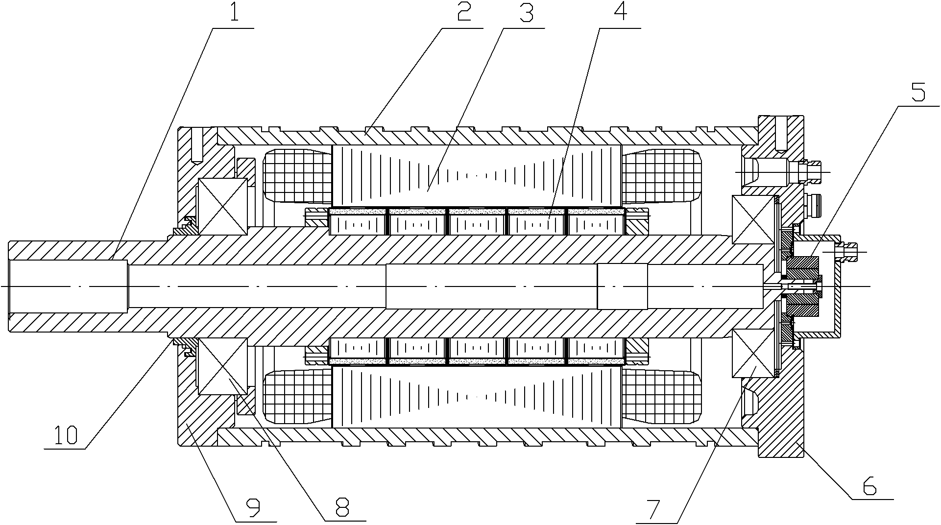
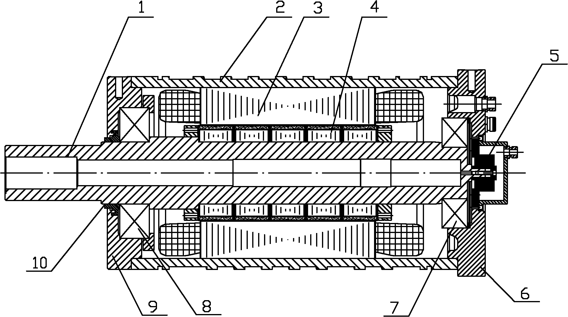
[0016] Such as figure 1 The shown AC permanent magnet synchronous spindle motor for tapping machine includes a housing 2, a rotating shaft 1, a permanent magnet rotor assembly 4, a stator assembly 3, an encoder 5, a front end cover 9 and a rear end cover 6. The front end cover 9 is installed on the front end of the casing 2, the rear end cover 6 is installed on the rear end of the casing 2, the rotating shaft 1 is arranged inside the casing 2 and is connected to the front end cover 9 and the The rear end cover 6 is connected, the permanent magnet rotor assembly 4 is installed on the rotating shaft 1, the stator assembly 3 is arranged on the inner wall of the housing 2 and corresponds to the permanent magnet rotor assembly 4, and the encoder 5 is installed on the rotating shaft The rear end of the shaft 1 and the encoder 5 are connected with an external driver, the rotating shaft 1 is a hollow structure, and the cross section of the hollow structure is variable. A sealing ring...


PUM


Abstract

The invention discloses an alternating current permanent magnet synchronous spindle motor for a threading machine. The motor comprises a shell, a rotating shaft, a permanent magnet rotor assembly, a stator assembly, an encoder, a front end cover and a rear end cover; the front end cover is mounted at a front end of the shell, and the rear end cover is mounted on a rear end of the shell; the rotating shaft is arranged in the shell, and respectively connected with the front end cover and the rear end cover through a first bearing and a second bearing; the stator assembly is arranged at the inner wall of the shell and located at the rear end of the shell; the permanent magnet rotor assembly is mounted on the rotating shaft; the encoder is mounted at the rear end of the rotating shaft and the encoder is connected with an external driver; and the rotating shaft is in a hollow structure, and the cross section of the hollow structure is a variable cross section. The motor provided by the invention can improve the working efficiency of the threading machine, has a simple structure and convenience, and is convenient for spread and use.

Description

technical field [0001] The invention relates to a spindle motor, in particular to an AC permanent magnet synchronous spindle motor used for a tapping machine. Background technique [0002] Tapping machine is a machine that processes internal threads, screws or tooth buttons on the inner surface of various parts with different specifications of through holes or blind holes, such as machine shells, equipment end faces, nuts, flanges, etc. Mechanical processing equipment. Tapping machine can be divided into manual tapping machine, pneumatic tapping machine, electric tapping machine and hydraulic tapping machine; according to the number of tapping machine spindles, it can be divided into single-axis tapping machine, two-axis tapping machine four Axis tapping machine, six-axis tapping machine, multi-axis tapping machine, etc. [0003] At present, for the electric tapping machine, its structure and speed regulating mechanism are relatively complicated, the rotational inertia of ...

Claims


Application Information

Patent Timeline
Patent Type & Authority Applications(China)
IPC IPC(8): H02K21/02
Inventor 尚立库焦春生张锐
Owner XIAN HESHENG POWER TECH CO LTD
Learn More