
Driving mechanism for pneumatic massager

A driving mechanism and massager technology, applied in vibration massage, massage auxiliary products, physical therapy, etc., can solve the problems of high noise, large gas loss, etc., and achieve the effect of reducing noise, comfortable massage, and low power

Inactive Publication Date: 2014-01-01
佛山市国亨家居科技有限公司
View PDF6 Cites 0 Cited by
  • Summary
  • Abstract
  • Description
  • Claims
  • Application Information

AI Technical Summary

Problems solved by technology

For the driving structure of the above-mentioned massager, there are the following deficiencies: (1) the air pump is difficult to circulate and discharge or inject the air between the two groups of connected airbags; (2) the gas loss is large; (3) the noise is large

Method used


Image

  • Driving mechanism for pneumatic massager
  • Driving mechanism for pneumatic massager
  • Driving mechanism for pneumatic massager

Examples


Embodiment Construction

[0013] The present invention will be described in further detail below in conjunction with the accompanying drawings.

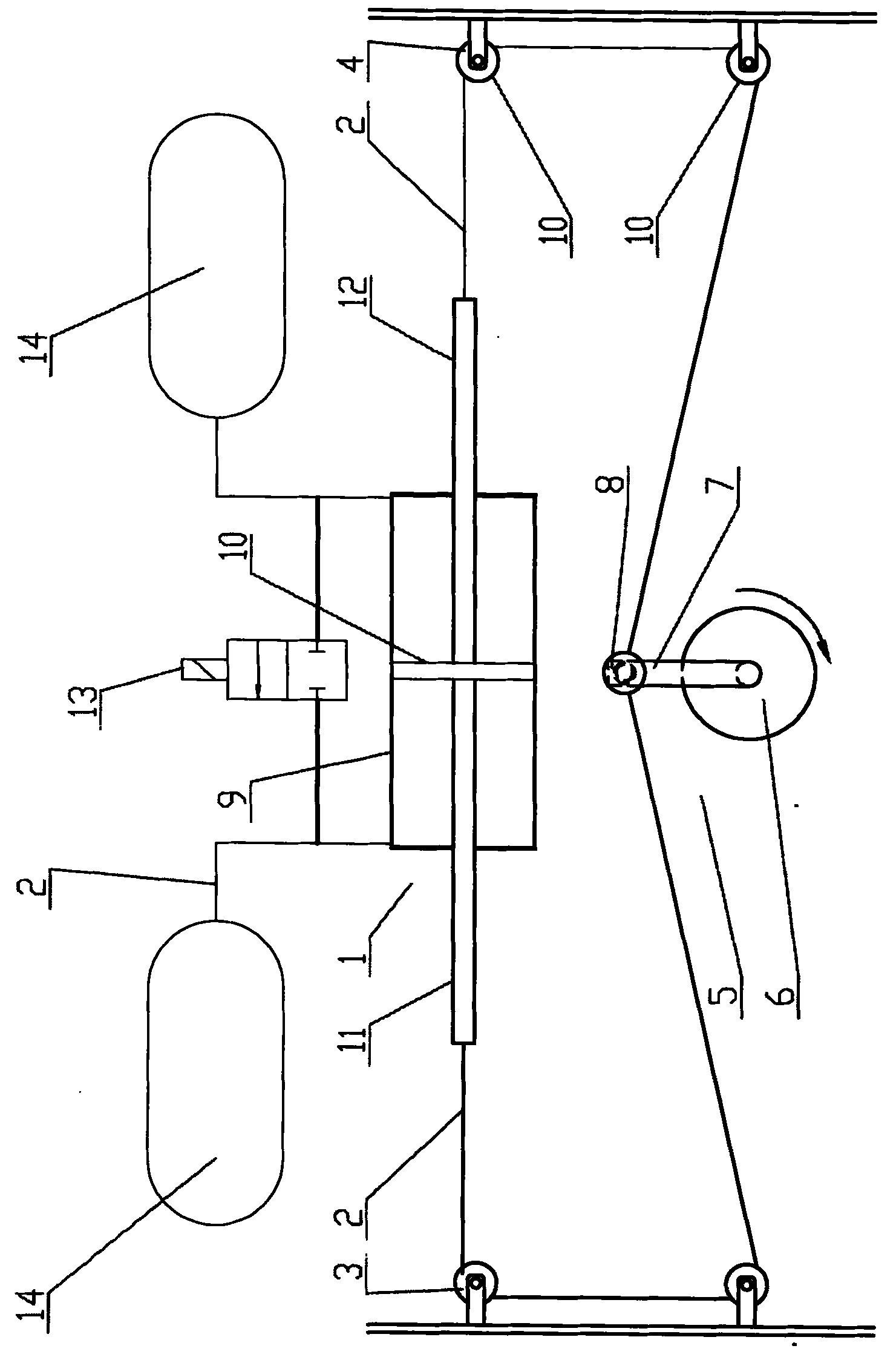
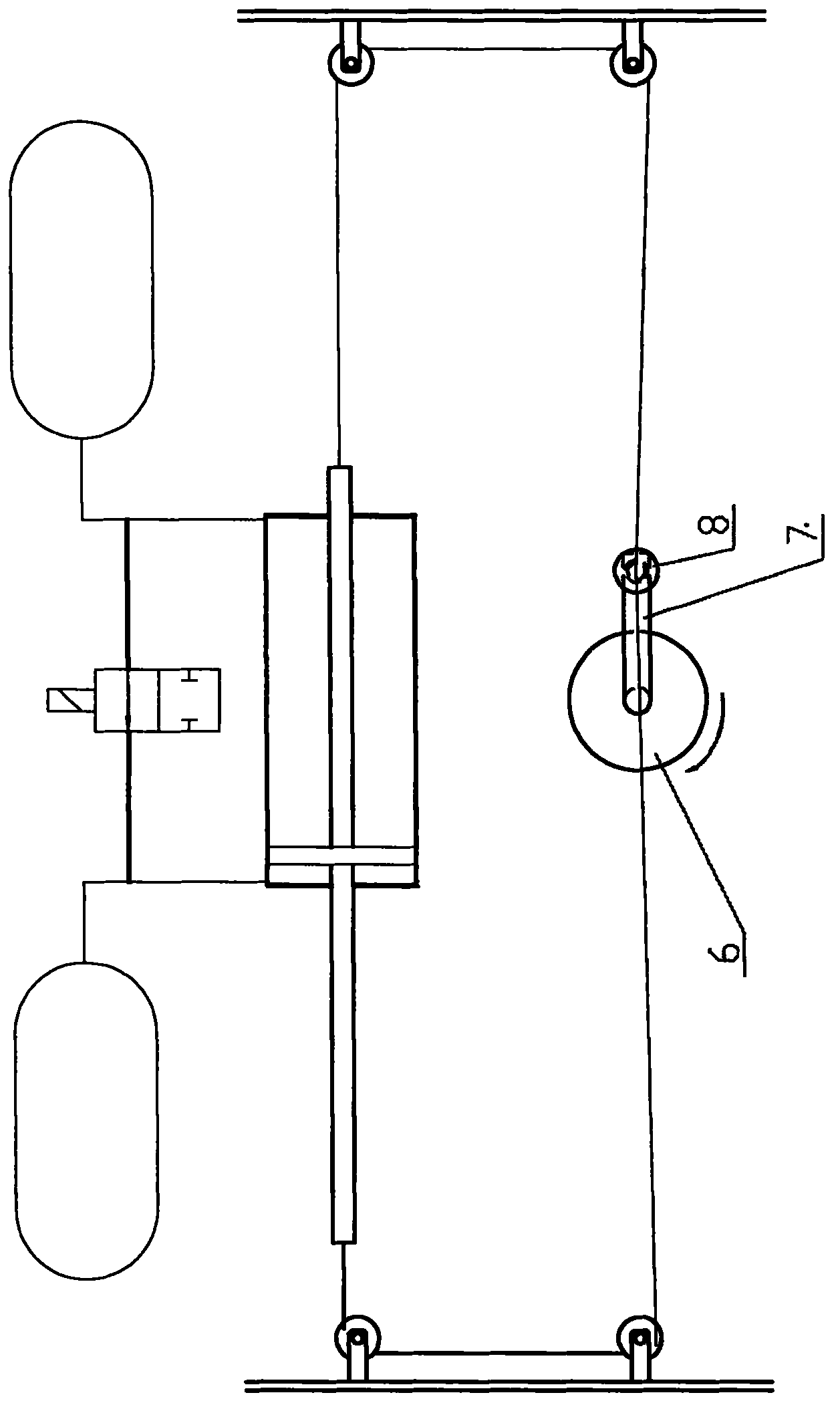
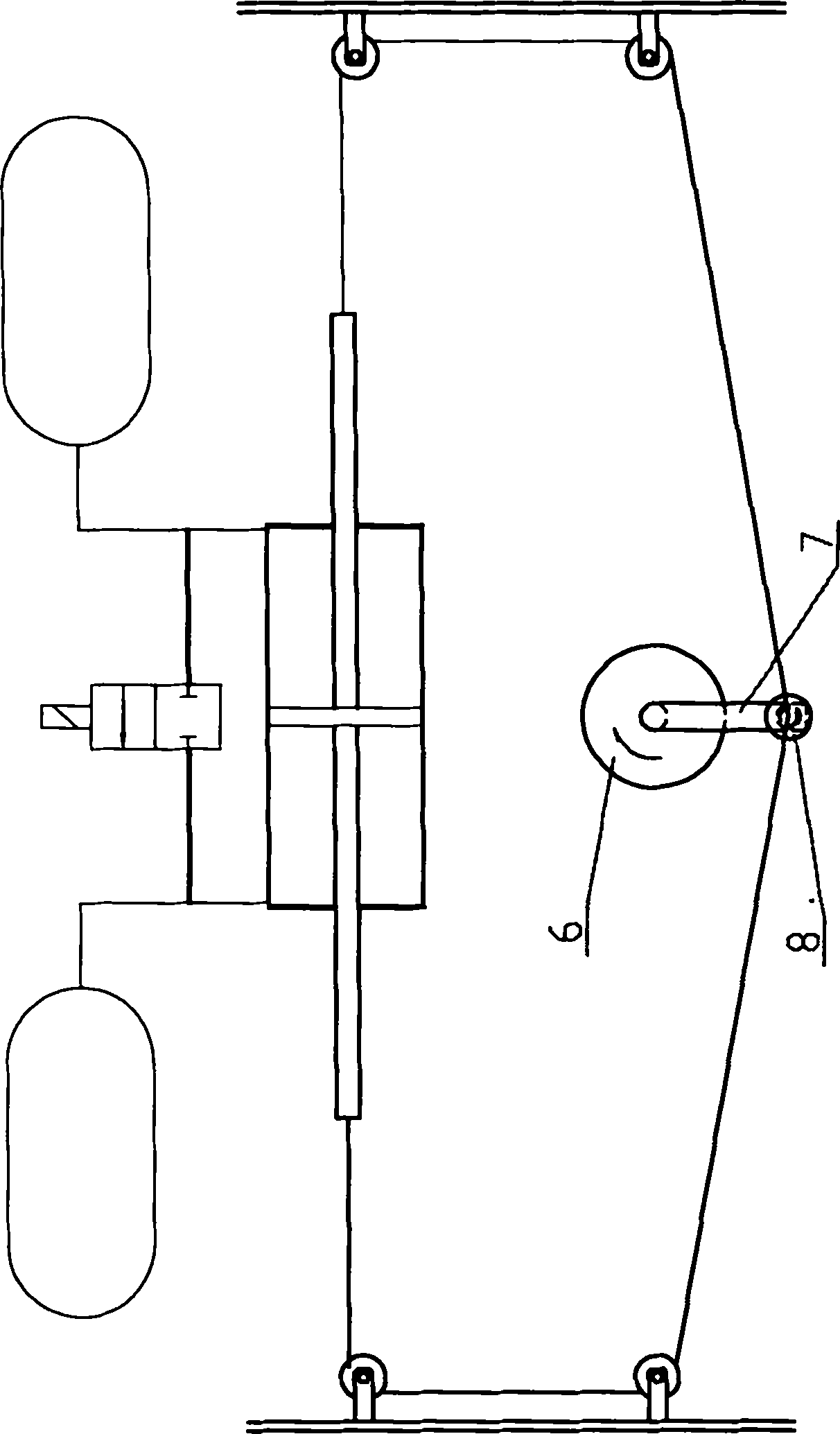
[0014] Such as Figure 1 to Figure 5 As shown, a driving mechanism of a pneumatic massager, the driving mechanism includes an air supply pump 1 communicated with the air bag 14 on the left and right sides, respectively connected to the left and right sides of the air supply pump 1 and capable of acting on the left and right sides of the air supply pump 1 One end of the steel wire rope 2 and one end of the steel wire rope 2 is connected to the left side of the air supply pump 1 and the other end passes through the left pulley 3 fixed on the left side. The right pulley 4 and the middle position of the wire rope 2 between the left pulley 3 and the right pulley 4 are provided with a power unit 5 acting on the left and right sides of the air supply pump 1; the power unit 5 includes a motor 6, an end and a motor The zigzag rotating arm 7 that 6 axis cores are fixe...


PUM


Abstract

The invention discloses a driving mechanism for a pneumatic massager. The driving mechanism is characterized by comprising an air supply pump of which the left and right sides are communicated with air bags, and a steel wire rope which is connected with the left and right sides of the air supply pump and can apply acting force to the left and right sides of the air supply pump, wherein one end of the steel wire rope is connected with the left side of the air supply pump; the other end of the steel wire rope passes through a left pulley which is fixedly arranged on the left side of the air supply pump; the steel wire rope which passes through the left pulley passes through a right pulley which is fixedly arranged on the right side of the air supply pump; and a power device for applying acting force to the left and right sides of the air supply pump is arranged at a middle position on the steel wire rope between the left pulley and the right pulley. The invention provides the driving mechanism by which air in two groups of communicated air bags can be circulated and which is used for the pneumatic massager with low noise, low power and a comfortable massage function.

Description

technical field [0001] The invention relates to a driving mechanism of a pneumatic massager. Background technique [0002] Because the pneumatic massager has the characteristics of soft massage and comfortable feeling, most of the various pneumatic massagers on the market use the air pump as the power in terms of their driving structure, and use the air pump to drive the gas to move the two groups of connected airbags. Exhaust gas or inject gas, so that the two groups of airbags can bulge or sag outwards to achieve the purpose of massage. For the driving structure of the above-mentioned massager, there are the following deficiencies: (1) the air pump is difficult to circulate and discharge or inject the air between the two groups of connected airbags; (2) the gas loss is large; (3) the noise is large . Contents of the invention [0003] In order to solve the above problems, the object of the present invention is to provide a driving mechanism for a pneumatic massager tha...

Claims


Application Information

Patent Timeline
Patent Type & Authority Patents(China)
IPC IPC(8): A61H23/04
Inventor 任汝刚梁昌勇
Owner 佛山市国亨家居科技有限公司
Learn More