Design method for friction pair of hydro-viscous driver (HVD)

A technology of liquid viscosity and friction pair, which is applied in the field of clutches and can solve problems such as speed difference

Inactive Publication Date: 2012-04-04
韩飞
View PDF0 Cites 8 Cited by
  • Summary
  • Abstract
  • Description
  • Claims
  • Application Information

AI Technical Summary

Problems solved by technology

The Newtonian shear force of the oil film drives the passive friction plate 10 to rotate in

Method used


Image

  • Design method for friction pair of hydro-viscous driver (HVD)
  • Design method for friction pair of hydro-viscous driver (HVD)
  • Design method for friction pair of hydro-viscous driver (HVD)

Examples


Embodiment Construction

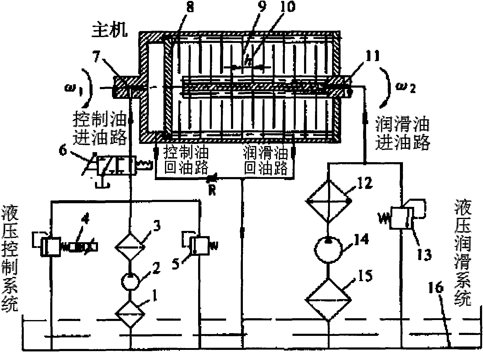
[0043] The technical solutions of the present invention will be further explained below in conjunction with the drawings and embodiments, but the following content is not intended to limit the protection scope of the present invention.

[0044] This embodiment provides a method for designing clutch friction pairs, which specifically includes the following steps:

[0045] 1 Obtain the rated load of the friction pair

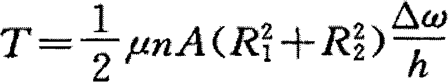
[0046] According to Newton's fluid shear theorem, the shear stress on the friction plate due to fluid viscosity at a radius r is

[0047] τ r = μ rΔω h - - - ( 1 )

[0048] In the formula, μ——oil dynamic viscosity; Δω——relative speed difference; h——oil film thickness

[0049] Both sides of formula (1) are multiplied by r, and both sides are from R 1 to R 2 Integral, the transfer torque of...


PUM


Abstract

The invention discloses a method for designing a clutch friction pair. The clutch is a hydro-viscous driver (HVD). The method comprises the following steps of: I, acquiring rated load of the friction pair; II, selecting a friction pair material; III, designing and verifying the inner and outer diameters of the friction pair; IV, designing an oil groove of the friction pair; and V, checking the working thermal balance of the friction pair. According to the invention, the friction pair is designed and checked by fully considering the working principle and practical working condition of the HVD, so that the performance requirement of practical engineering on the HVD can be met actually. The friction pair designed with the method can be widely applied to industrial fields of HVD variable-speed energy-saving systems such as thermal power plants, water plants, chemical plants and the like. As proved by experiments, the method can fully meet the practical requirement of engineering.

Description

technical field [0001] The invention relates to a clutch, in particular to a method for designing a clutch friction pair. Background technique [0002] The working performance of the hydraulic viscous clutch (referred to as HVD) is related to many factors, and the transmission friction pair as the core of its power transmission is the key. The traditional design of HVD friction pair is directly borrowed from the design method of ordinary wet clutch friction pair. This design method is applied to some medium and small power level HVDs or applications where the accuracy of HVD speed regulation is not high, and it can basically meet the engineering needs; With the development of the direction, this kind of design method that completely borrows the friction pair of ordinary wet clutch has been increasingly unable to meet the high performance requirements put forward by the actual engineering. Therefore, it is necessary to study the design and calibration methods of the frictio...

Claims


Application Information

Patent Timeline
IPC IPC(8): F16D13/54F16D13/60
Inventor 韩飞
Owner 韩飞
Why Eureka
Try Eureka