High-efficiency numerical-control drilling-milling machine tool

A processing machine tool, drilling and milling technology, applied in the field of high-efficiency CNC drilling and milling machine tools, can solve the problems of low processing efficiency, low drag acceleration, and rapid attenuation of positioning accuracy, and achieve the advantages of improving processing efficiency, high positioning accuracy, and eliminating attenuation. Effect

Inactive Publication Date: 2014-06-18
宁波市凯博数控机械有限公司
View PDF8 Cites 16 Cited by
  • Summary
  • Abstract
  • Description
  • Claims
  • Application Information

AI Technical Summary

Problems solved by technology

[0002] The manufacturing and processing of equipment, such as injection molds, requires drilling, tapping, and milling a large number of through holes, blind holes, threaded holes, stepped counterbores, grooves, tenons, tenons and slide rails of various shapes on the workpiece , chute and other hole-groove-rail structures, usually the CNC machining center is used to perform drilling, tapping and milling of the hole-groove tenon-rail structure while processing the workpiece surface structure; the prior art CNC machining center uses a rotary servo motor plus a ball screw The auxiliary drags the X, Y, Z skateboard movement to realize three-dimensional cutting processing. Since the rotary servo motor needs to convert the rotary motion into the linear reciprocating motion of the dragging skateboard through the ball screw pair, the dragging speed is slow, and the dragging speed is less than or equal to 100 meters. / minute; dragging acceleration is low, the maximum acceleration is 1.5g, which leads to slow three-dimensional homing speed of the machine tool and low processing efficiency; in addition, because the ball screw pair is easy to produce gaps due to work wear, the positioning accuracy of the machine tool three-dimensional homing decays quickly ; Due to the limitation of material elasticity, the ball screw pair should not be too long, which limits the length of the working stroke of the CNC machining center; therefore, the existing technology has the problems and deficiencies of low search efficiency, fast decay of positioning accuracy, and limited working stroke

Method used


Image

  • High-efficiency numerical-control drilling-milling machine tool
  • High-efficiency numerical-control drilling-milling machine tool
  • High-efficiency numerical-control drilling-milling machine tool

Examples


Embodiment Construction

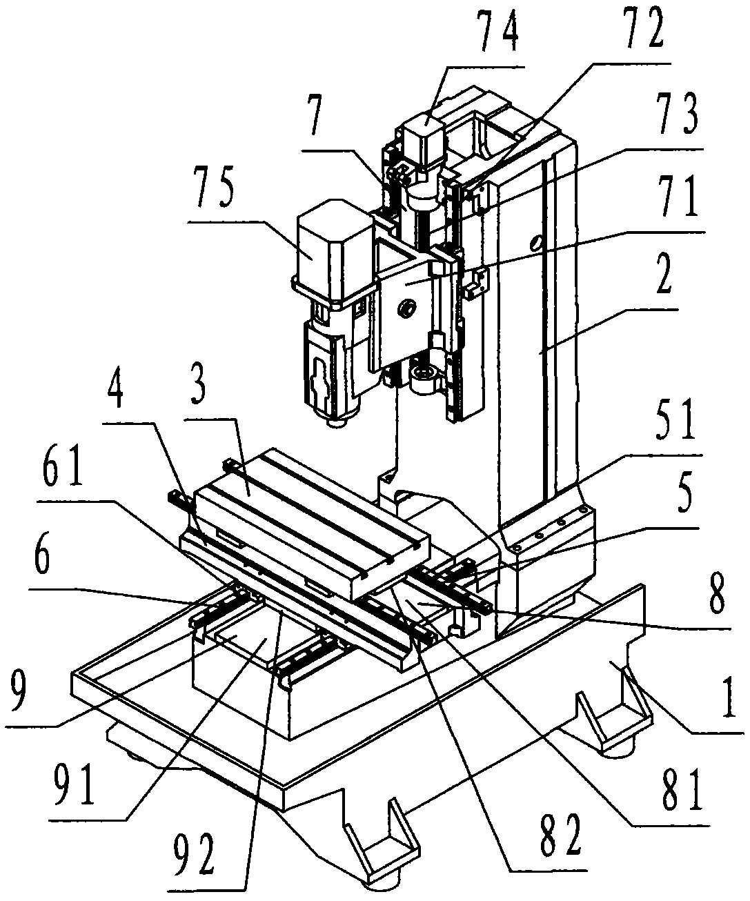
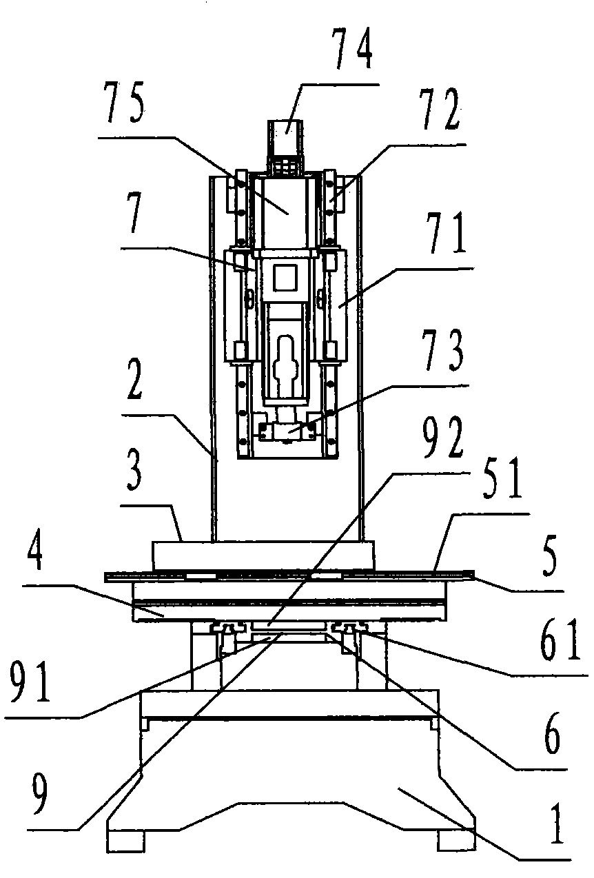
[0028] refer to Figure 1 ~ Figure 2 , a high-efficiency CNC drilling and milling machine tool of the present invention, including a bed 1, a column 2, a workbench 3, an orthogonal carriage 4, an X slide pair 5, a Y slide pair 6, a Z slide pair 7, and a spindle Motor 75, X-axis linear motor 8, and Y-axis linear motor 9, wherein: the bed 1 is a rectangular platform-shaped hollow cast iron member, the bottom four corners of the bed 1 are provided with bed feet, and the upper edge of the bed 1 There is an upwardly protruding frame. The middle and rear part of the bed 1 is symmetrically provided with two upwardly protruding groove-shaped bosses in the front and rear directions along the center line of the long side, which are called Y-axis connecting seats. The bed 1 The hollow inner wall is provided with criss-cross reinforcement ribs;

[0029] The column 2 is a rectangular columnar hollow cast iron component, and the upper middle part of the front of the column 2 is provided wi...


PUM


Abstract

The invention discloses a high-efficiency numerical-control drilling-milling machine tool. The high-efficiency numerical-control drilling-milling machine tool comprises a bed (1), a stand column (2), a worktable (3), an orthogonal carriage (4), an X slide seat pair (5), a Y slide seat pair (6), a Z slide seat pair (7), a main shaft motor (75), an X-shaft linear motor (8) and a Y-shaft linear motor (9). An X-shaft slide plate and a Y-shaft slide plate are dragged by the linear motor, a Z-shaft slide plate is dragged by a rotating servo motor and a ball screw assembly to drill and mill a three-dimensional seek, so that the problems and weaknesses of the prior art that the efficiency of the seek is low, the attenuation of the positioning precision is fast, and the working stroke is limited can be overcome; by adopting the characteristics of the linear motor that the dragging speed is high, the acceleration is high, the positioning precision is high, the abrasion attenuation is avoided and the traveling stroke is not limited, the seek efficiency is improved, the attenuation of the positioning precision is eliminated and the traveling length is not limited by adopting the numerical-control drilling-milling machine tool.

Description

technical field [0001] The invention relates to a numerical control cutting machine tool, in particular to a high-efficiency numerical control drilling and milling machine tool specially used for drilling, tapping and milling on workpieces. Background technique [0002] The manufacturing and processing of equipment, such as injection molds, requires drilling, tapping, and milling a large number of through holes, blind holes, threaded holes, stepped counterbores, grooves, tenons, tenons and slide rails of various shapes on the workpiece , chute and other hole-groove-rail structures, usually the CNC machining center is used to perform drilling, tapping and milling of the hole-groove tenon-rail structure while processing the workpiece surface structure; the prior art CNC machining center uses a rotary servo motor plus a ball screw The auxiliary drags the X, Y, Z skateboard movement to realize three-dimensional cutting processing. Since the rotary servo motor needs to convert th...

Claims


Application Information

Patent Timeline
Patent Type & Authority Applications(China)
IPC IPC(8): B23P23/00B23Q5/34B23Q5/40B23Q5/36
CPCB23Q1/015B23P23/02B23Q1/585B23Q1/621B23Q1/70B23Q5/40B23Q2705/14
Inventor 伍爱民黄吉能徐建国俞湘王可长沈良永
Owner 宁波市凯博数控机械有限公司
Why Eureka
Try Eureka