Air tunnel fast braking test system

A brake test and brake system technology, applied in the field of test systems for testing vehicle performance, can solve problems such as low safety factor, cumbersome operation, and easy accidents, and achieve the effects of improved safety, simple and convenient operation, and reduced pressure

Inactive Publication Date: 2012-04-04
无锡市锦华试验设备有限公司
View PDF4 Cites 4 Cited by
  • Summary
  • Abstract
  • Description
  • Claims
  • Application Information

AI Technical Summary

Problems solved by technology

see image 3 , because in the process that movable damper 4 is closed, movable damper 4 will bear the wind pressure of huge horizontal direction (direction of arrow is air flow direction), easily cause accident, make th

Method used


Image

  • Air tunnel fast braking test system
  • Air tunnel fast braking test system
  • Air tunnel fast braking test system

Examples


Embodiment Construction

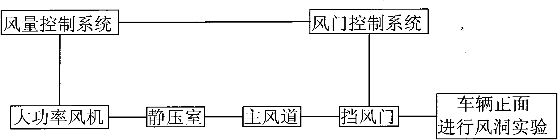
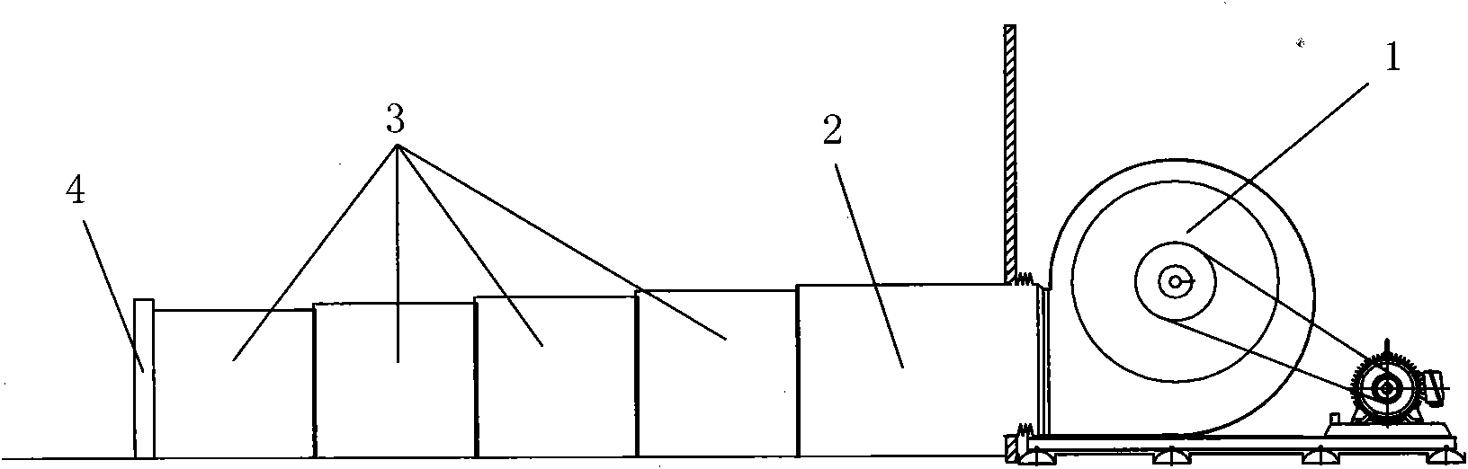
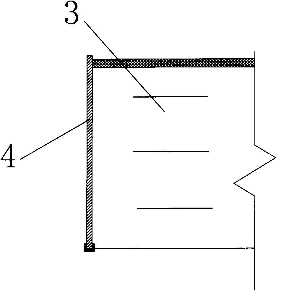
[0017] see Figure 4-6 , a fast braking test system in a wind tunnel, comprising a damper control system, an air volume control system, a blower fan 1, a static pressure chamber 2, a main air duct 3 and a movable damper 4, and the damper control system is respectively connected with the air volume control system and the static pressure Room 2 is connected, and the air volume control system is also connected with fan 1. Fan 1, plenum chamber 2 and main air duct 3 are sequentially arranged to form an air flow channel. The air flow output by fan 1 enters the active air duct 4 through plenum chamber 2, The wind tunnel quick braking test system also includes a secondary air duct 5 communicating with the static pressure chamber 2, and an air deflector 6 communicating with the secondary air duct 5 and the test space is arranged on the air outlet of the secondary air duct 5; 4 is set in the static pressure chamber 2, and a piston cylinder 7 that supports and adjusts the position of th...


PUM


Abstract

The invention relates to an air tunnel fast braking test system which is arranged in a test space and comprises an air door braking system, an air quantity control system, a fan, a static pressure chamber, a main air channel and a movable air door, wherein the air door control system is connected with the air quantity control system and the static pressure chamber respectively; the air quantity control system is connected with the fan; the fan, the static pressure chamber and the main air channel are sequentially arranged to form an airflow channel; the an air tunnel fast braking test system is characterized in that the air tunnel fast braking test system also comprises a secondary air channel which is communicated with the static pressure chamber; an air guide plate used for communicating the secondary air channel and the test space is arranged on an air outlet of the secondary air channel; the movable air door is arranged in the static pressure chamber; a supporting and adjusting mechanism used for supporting and adjusting the position of the movable air door is also arranged in the static pressure chamber; and an air quantity adjustor is arranged on an air outlet of the main air channel. The air tunnel fast braking test system is simple and convenient in operation and high in safety.

Description

technical field [0001] The invention relates to a test system for testing automobile performance, in particular to a wind tunnel fast braking test system. Background technique [0002] see figure 1 , figure 2 , the wind tunnel rapid braking test system in the prior art includes a damper control system, an air volume control system, a fan 1, a static pressure chamber 2, a main air duct 3 and a movable damper 4, and the damper control system is respectively connected with the air volume control system and the air volume control system. The static plenum 2 is connected, and the air volume control system is also connected with the fan 1. The fan 1, the static plenum 2 and the main air duct 3 are sequentially arranged to form an air flow channel, and the movable damper 4 is arranged at the air outlet of the main air duct 3. When performing a quick braking test for a car, place the car in front of the movable air duct 4, and the measurable airflow generated by the fan 1 directl...

Claims


Application Information

Patent Timeline
IPC IPC(8): G01M17/007G01M9/02
Inventor 单金华
Owner 无锡市锦华试验设备有限公司
Why Eureka
Try Eureka