Light guide for endoscope, endoscope equipped with light guide, and method for producing light guide for endoscope

An endoscope and light guide technology, which is applied to endoscopes and manufactures light guides for endoscopes, can solve problems such as harm to the human body

Active Publication Date: 2012-04-04
FUJIFILM CORP
View PDF7 Cites 7 Cited by
  • Summary
  • Abstract
  • Description
  • Claims
  • Application Information

AI Technical Summary

Problems solved by technology

[0005] However, from the viewpoint of the safety standard of the laser beam, forming the output end of the optical fiber to be as thin as disclosed in Japanese Unexamined Patent Publication No. 2009-297188 causes various problems
There are cases where a laser beam emitted by a laser light source will be harmful to the human body due to the high power density per viewing angle of the laser beam even if the emission amount is low

Method used


Image

  • Light guide for endoscope, endoscope equipped with light guide, and method for producing light guide for endoscope
  • Light guide for endoscope, endoscope equipped with light guide, and method for producing light guide for endoscope
  • Light guide for endoscope, endoscope equipped with light guide, and method for producing light guide for endoscope

Examples


Embodiment approach

[0078] Embodiments of the light guide for endoscopes of the present invention will be described below.

Embodiment approach 1

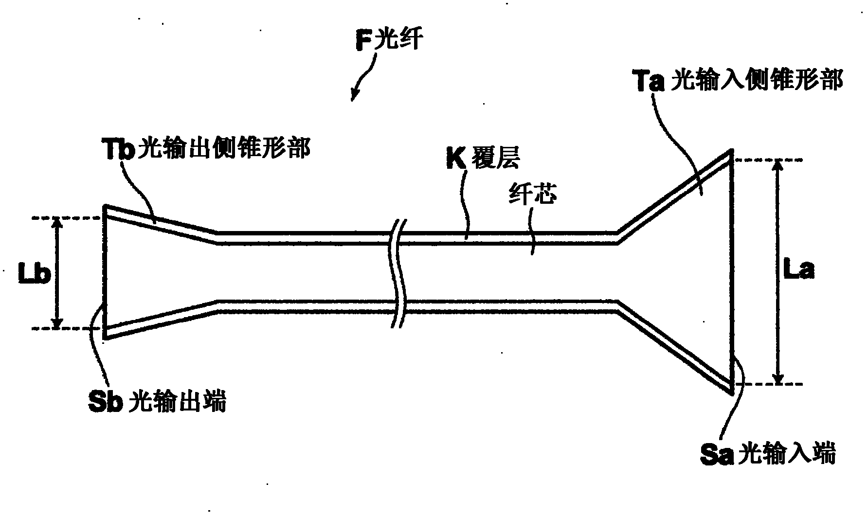
[0080] Two silica multimode optical fibers were prepared, the straight portion of the optical fiber had a numerical aperture NA of 0.22, a core diameter of 200 μm, a cladding diameter of 240 μm, and a total length of 2.5 m, and a tapered treatment was performed on the optical fibers so that the The first end of the optical fiber has a tapered shape that becomes thicker towards the end. One of the two optical fibers is tapered so that tapering starts at a position 50 cm away from the first end, and the core diameter at the first end is 700 μm. The other of the two optical fibers is tapered so that the tapering starts at a position 50 cm away from the first end, and the core diameter at the first end is 300 μm. Subsequently, the thin-diameter ends (ends not subjected to tapering processing) of the first optical fiber and the second optical fiber were melted. Therefore, an optical fiber bundle having a light-input-side tapered portion thickened toward an end having a core diamet...

Embodiment approach 2

[0083] Two silica multimode optical fibers are prepared, the linear portion of the optical fiber has a numerical aperture NA of 0.5, a core diameter of 100 μm, a cladding diameter of 115 μm, and a total length of 2.5 m, and the optical fiber is tapered so that The first end of the optical fiber has a tapered shape that becomes thicker toward the end. One of the two optical fibers is tapered so that tapering starts at a position 50 cm away from the first end, and the fiber core diameter at the first end is 700 μm. The other of the two optical fibers is tapered so that tapering starts at a position 50 cm away from the first end, and the core diameter at the first end is 300 μm. Subsequently, the thin-diameter ends (ends not subjected to tapering treatment) of the first optical fiber and the second optical fiber were melted. Therefore, an optical fiber bundle having a light-input-side tapered portion thickened toward an end having a core diameter of 700 μm at the end and a light...


PUM

PropertyMeasurementUnit
diameteraaaaaaaaaa
diameteraaaaaaaaaa
diameteraaaaaaaaaa

Abstract

The present invention discloses a light guide for an endoscope. The light guide for an endoscope is equipped with an optical fiber. The optical fiber has an input side tapered portion and an output side tapered portion. The input side tapered portion is a predetermined portion of the optical fiber that includes an input end into which the illumination light enters the optical fiber, and the core of the optical fiber having a shape that becomes thicker toward the input end in the light input side tapered portion. The light output side tapered portion is a predetermined portion of the optical fiber that includes an output end through which the illumination light is output, and the core of the optical fiber having a shape that becomes thicker toward the output end in the light output side tapered portion. The core diameter at the input end is greater than the core diameter at the output end.

Description

technical field [0001] The present invention relates to a light guide for an endoscope that is inserted into a body cavity and guides illumination light to a portion to be observed, and to an endoscope equipped with the light guide. The invention also relates to a method for manufacturing a light guide for an endoscope. Background technique [0002] Endoscopic systems for viewing tissue in body cavities are widely known. For example, an endoscope system that obtains a visible image by imaging a portion to be observed in a body cavity illuminated with white light and displays the visible image on a screen of a monitor is widely used in practice. [0003] A light guide for an endoscope for introducing illumination light into a body cavity is used in the aforementioned endoscope system. A laser light source can be used as a light source for generating illumination light. [0004] A light guide for an endoscope equipped with an optical fiber for guiding illumination light int...

Claims


Application Information

Patent Timeline
Patent Type & Authority Applications(China)
IPC IPC(8): G02B6/00A61B1/07
CPCG02B23/2469A61B1/07A61B1/05Y10T29/49826
Inventor 吉田光治吉弘达矢
Owner FUJIFILM CORP
Why Eureka
Try Eureka