
High-brightness LED illumination dodging system

A LED lighting and high-brightness technology, applied in the field of projection and micro-projection, can solve the problems of difficulty in meeting the requirements of instrument miniaturization, large volume, and increased cost, and achieve the goal of improving energy collection efficiency, reducing volume, and reducing light loss Effect

Active Publication Date: 2013-06-26
SUZHOU INST OF BIOMEDICAL ENG & TECH
View PDF5 Cites 0 Cited by
  • Summary
  • Abstract
  • Description
  • Claims
  • Application Information

AI Technical Summary

Problems solved by technology

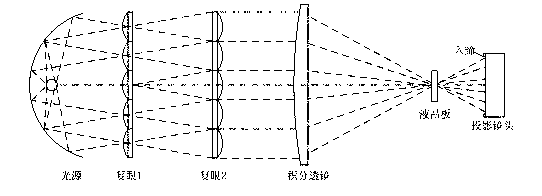
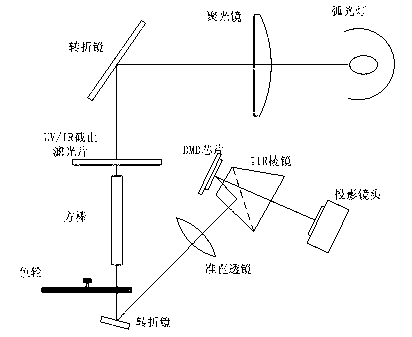
[0007] The above-mentioned traditional projection lighting systems all use condenser lens groups for light coupling and uniform illumination. This method uses a lens group composed of multiple lenses, which greatly increases the cost, and the volume is relatively large, which is difficult to meet the miniaturization of the instrument. requirements

Method used


Image

  • High-brightness LED illumination dodging system
  • High-brightness LED illumination dodging system
  • High-brightness LED illumination dodging system

Examples


Embodiment 1

[0036] Such as Figure 4 As shown, a high-brightness LED lighting uniform light system is shown, which includes a high-brightness LED module 1, and an LED light-emitting chip 2 is arranged on the high-brightness LED module 1, and the positive side of the LED light-emitting chip 2 is The front is provided with a homogenizing rod, and a color wheel 7 is arranged directly in front of the homogenizing rod. The homogenizing rod includes a tapered structure part 3, and the size of the incident end of the tapered structure part 3 is smaller than that of the outgoing end. Size, the incident end face of the tapered structure part 3 is rectangular or other shapes, its size is preferably close to the size of the light source, the outgoing end face is a rectangular structure, and the aspect ratio of the rectangular structure is 4:3 or 16:9 , the floating range is within 10%.

[0037] The homogenizing rod further includes a rectangular structure part 4, which is located at the incident en...

Embodiment 2

[0043] Such as Figure 5 As shown, a high-brightness LED lighting uniform light system is shown, and the main difference from Embodiment 1 is that the rectangular structure part 4 of the light uniform rod is in the direction close to the LED light-emitting chip 2. This structure is essentially the same as that of Embodiment 1. The above are the same, and the energy coupling efficiency is equivalent. The main reason is that the position of the positioning plate 5 of the uniform light rod is close to the high-brightness LED module 1, which changes the clamping method of the fixture.

Embodiment 3

[0045] Such as Figure 6 As shown, a high-brightness LED lighting homogenization system is shown, and the main difference from Embodiment 1 is that the structure of the homogenization rod has changed, which only consists of a tapered structure part 3 and does not include a rectangular structure part 4 . The incident end face of the tapered structure part 3 is rectangular or other shapes, and its size is preferably close to the size of the light source, and the outgoing end face is a rectangular structure, and the aspect ratio of the rectangular structure is 4:3 or 16:9 (or approximately Proportion). This structure is essentially the same as Embodiment 1, and the energy coupling efficiency is equivalent, mainly because the rectangular structure part 4 of the dodging rod is omitted, and the clamping mode of the clamp is changed at the same time.


PUM


Abstract

The invention discloses a high-brightness LED illumination dodging system, which comprises a high-brightness LED module; the high-brightness LED module is provided with an LED light-emitting chip; a dodging bar is disposed in front of the LED light emitting chip; a color wheel is disposed in front of the dodging bar; the dodging bar includes a conical structure part, and size of incident end of the conical structure part is smaller than that of emergent end thereof; and the emergent end surface of the conical structure part is a rectangular structure, and the length-to-width ratio of the rectangular structure is 4:3 or 16:9, along with variation range of below 10%. The illumination dodging system can not only greatly improve energy collection efficiency of the LED light source and improveuniformity of the emergent light, but also change shape of the emergent light spot according to need of projection illumination so as to shorten volume of coupling device, so that the system is suitable for requirements of the field of projection, in particular micro projection on brightness and volume of illumination light source.

Description

technical field [0001] The invention belongs to the field of projection, especially the field of micro-projection, and in particular relates to an illumination homogenization system for improving the uniformity of emitted light from an LED light source and changing the shape of the emitted light spot. Background technique [0002] The projection system is a technology that projects information such as moving images or still pictures onto a screen to display specific information to people. With the advent of the information society, projection display technology has entered an era of diversity. In recent years, micro-projectors have been widely used in the field of business projection due to their portability and dexterity. With the emergence of chips, mobile phone projection technology is also rapidly rising. [0003] At present, in order to reduce energy consumption, improve safety, and adapt to the development trend of miniaturization in the field of projection, especiall...

Claims


Application Information

Patent Timeline
Patent Type & Authority Patents(China)
IPC IPC(8): G03B21/20G02B27/09F21V13/00F21Y101/02
Inventor 杨西斌朱剑锋李蕊熊大曦
Owner SUZHOU INST OF BIOMEDICAL ENG & TECH
Learn More