
Light guide plate for advertisement light box and manufacturing method of light guide plate

A technology for advertising light boxes and manufacturing methods, which is applied in the direction of light guides, optics, optical components, etc., can solve the problems of expensive manufacturing costs, low uniformity, and high cost of abrasive tools, and achieve reduction of light pollution emissions. The method is simple and easy, The effect of reducing processing costs

Inactive Publication Date: 2011-08-17
CHENGDU BENLIU LOGO MFG
View PDF6 Cites 0 Cited by
  • Summary
  • Abstract
  • Description
  • Claims
  • Application Information

AI Technical Summary

Problems solved by technology

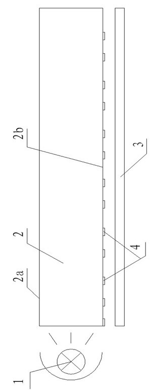
However, for the light guide plate produced by the above method, the bottom of the light guide plate is silk-screened, which can only play a role of reflection. For the bottom surface of the light guide plate far away from the light source, the light is weak, which makes the uniformity effect of the light-emitting surface of the entire light guide plate Not good; the V-cutting method is dotted on the bottom surface, and the reflective surface is formed through a dot matrix. The uniformity effect is better, but the cost is expensive, and the brightness of the light guide plate does not meet the requirements; the way of printing dots, the reverse effect is not good , the uniformity is not high, the brightness is not enough; laser, sandblasting, chemical etching and other methods are the same as above, there are problems such as thicker light-transmitting plate, low light efficiency, uniformity that cannot meet the requirements, and insufficient brightness.
[0004] The application number is 200310117597.X, the application date is December 20, 2003, the publication number CN1629692A, the publication date is June 22, 2005, and the Chinese invention patent application named light guide plate and its manufacturing method discloses a light guide A light plate and its manufacturing method. The light guide plate mainly distributes filiform protrusions on the light-emitting surface, and a plurality of scattering points are made on the bottom of the light guide plate. Although the light emitted from the light source can be reflected to the light-emitting surface through the scattering points, and the The filamentary protrusions on the surface disperse the light evenly, but because the light source is installed on one side of the light guide plate, the distance of light irradiation is limited, and the brightness of the light guide plate far away from the light source is not enough, so that the brightness of the light-emitting surface of the entire light guide plate And the uniformity is not enough. If the light source is installed on multiple sides, it will cause power consumption, increase the cost of use, and is not environmentally friendly
The manufacturing method in the patent application for this invention uses wire-drawing abrasives to form filamentous protrusions on the light-emitting surface. The filamentary protrusions are mainly for the purpose of uniformizing the light to be emitted. However, due to the high manufacturing cost of the abrasives, the entire light guide plate cannot The cost is high, and its wire drawing structure is located on the light-emitting surface. The filamentary protrusions on the light-emitting surface only homogenize the light to be emitted, but do not effectively lead out all the light from the light source, resulting in partial light not being fully utilized. increase power consumption
[0005] The application number is 200410051215.2, the application date is August 22, 2004, the publication number is CN1737660A, and the publication date is February 22, 2006. The Chinese invention patent application named light guide plate discloses a light guide plate. The uniformity of light is achieved by setting V-shaped grooves on the reflective surface and the outgoing surface of the light guide plate, and the V-shaped grooves on the two surfaces are perpendicular to each other, but the structure of this light guide plate is complicated, the processing cost is expensive, and the The V-shaped grooves on both sides of the light guide plate are respectively distributed in parallel, and the light source is installed on one side of the light guide plate. The light enters from the side of the light guide plate. The phenomenon that part of the light cannot be emitted to the exit surface is manifested in the light track on the surface of the light guide plate, which is reduced by the V-shaped grooves perpendicular to each other on the two surfaces, but there will still be local shadows The intersection point forms a dead point, which makes the uniformity of the light on the surface of the entire light guide plate insufficient. At the same time, the light passes through the V-shaped groove for two or three times, and the light exiting the guide line becomes chaotic and difficult to control. places where the light is dim

Method used


Image

  • Light guide plate for advertisement light box and manufacturing method of light guide plate
  • Light guide plate for advertisement light box and manufacturing method of light guide plate
  • Light guide plate for advertisement light box and manufacturing method of light guide plate

Examples


Embodiment 1

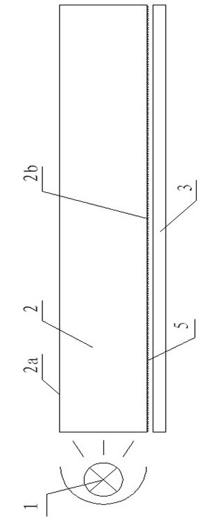
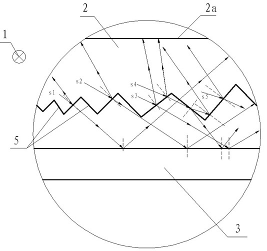
[0038] Example 1 as figure 1 , figure 2 and image 3 As shown, the light guide plate for advertising light boxes of the present invention includes a light source 1, a light-transmitting plate 2 and a reflector 3, the reflector 3 is located below the bottom surface 2b of the light-transmitting plate 2, and the light source 1 is located at the bottom of the light-transmitting plate 2 On the side, the bottom surface 2b of the transparent plate 2 is provided with a plurality of concave, linear reflective grooves 5, the reflective grooves 5 are regularly distributed on the bottom surface 2b of the transparent plate 2, the reflective The farther the groove 5 is from the light source 1, the denser the density and the deeper the depth. The reflective groove 5 has a width ranging from 0 to 200 microns and a depth ranging from 0 to 200 microns. 5 is a V-shaped structure, and the transparent plate 2 is made of polycarbonate. Light guide plate for advertising light box of the present...

Embodiment 2

[0039] Embodiment 2 is similar to Embodiment 1, the difference is that the reflective groove 5 is an arc-shaped structure, and the light-transmitting plate 2 is made of polymethyl methacrylate, and the reflective groove 5 of the arc-shaped structure It is also possible to guide the stronger light part to the side away from the light source 1 through the reflection and refraction of the light, so that the light of the entire light guide plate is uniform, and the light effect is better and the brightness is brighter. The thickness of the light guide plate for the advertising light box can be It is thinner, has lower cost, and consumes less energy, and the light-transmitting plate 2 is made of polymethyl methacrylate, so that the light-transmitting property of the entire light-transmitting plate 3 is better and the service life is longer.

Embodiment 3

[0040] Embodiment 3 is similar to Embodiment 1 and Embodiment 2, except that the reflective groove 5 is a trapezoidal structure, and the reflective groove 5 of the trapezoidal structure can reflect light due to its inclined structure on one or both sides. And refraction, it can also guide part of the light source from the side close to the light to the side far away from the light source, so that the light of the light guide plate for the entire advertising light box is uniform, and the light effect is better and the brightness is brighter. The thickness can be made thinner, the cost is lower, and the energy consumption is less.

[0041] The manufacturing method of the light guide plate for the advertising light box of the present invention comprises the following steps: making the body of the light-transmitting plate 2; processing the bottom surface 2b of the light-transmitting plate 2 by a mechanical drawing process, so that the bottom surface 2b of the light-transmitting pla...


PUM


Abstract

The invention discloses a light guide plate for an advertisement light box and belongs to the field of the light guide plate for the advertisement light box. The light guide plate comprises a light source (1), a light-transmitting board (2) and a reflection board (3), wherein the reflection board (3) is arranged under the bottom side (2b) of the light-transmitting board (2); the light source (1) is arranged at side edge of the light-transmitting board (2); and the bottom side (2b) of the light-transmitting board (2) is provided with a plurality of inwards-concave linear structured reflection slots (5). The light guide plate for the advertisement light box provided by the invention is manufactured by using the wire drawing technique, the processing cost is low, the structure is simple, the manufacturing is convenient, the degree of uniformity is high, the lighting effect is high, the luminance is high, the volume is small, the weight is light, the cost is low and the popularization is easily realized. A surface light source can be formed by the reflection lights of the slots on the bottom of the light-transmitting board, thereby avoiding forming a blind channel and reducing the emission of light pollution.

Description

technical field [0001] The invention relates to a manufacturing technology of a light guide plate used on an advertising light box, in particular to a light guide plate used on an advertising light box and a manufacturing method thereof. Background technique [0002] At present, the light guide plates used in advertising light boxes are derived from liquid crystal display technology. Since the liquid crystal in the LCD panel itself does not have light-emitting characteristics, in order to achieve realistic effects, it is necessary to provide a light source device for the LCD panel, such as a backlight module, whose function is to supply the LCD panel with a light source with sufficient brightness and uniform distribution. . The advertising light box also adopts this principle to ensure that the light source of the advertising light box is uniform. [0003] Prior art light guide plates, such as figure 1 As shown, it is composed of a light source, a light-transmitting plate...

Claims


Application Information

Patent Timeline
Patent Type & Authority Applications(China)
IPC IPC(8): G02B6/00G09F13/04F21V13/00
Inventor 李晓红
Owner CHENGDU BENLIU LOGO MFG
Learn More