
Fiber Taper

A technology of optical fiber cones and fiber filaments, which is applied in the direction of bundled optical fibers, etc., can solve the problems of low utilization rate of cone rods, reduced coupling efficiency of cone rods, and inability of cone rods to have the effect of uniform light, so as to improve utilization rate and improve Effect of Optical Coupling Efficiency

Active Publication Date: 2018-12-18
SUZHOU INST OF BIOMEDICAL ENG & TECH CHINESE ACADEMY OF SCI
View PDF4 Cites 0 Cited by
  • Summary
  • Abstract
  • Description
  • Claims
  • Application Information

AI Technical Summary

Problems solved by technology

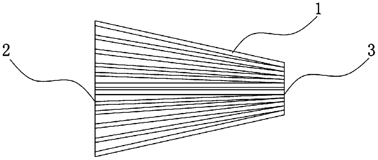
[0003] like figure 1 As shown, in the current optical fiber taper, the positions of the entrance and exit of the optical fiber 1 are in one-to-one correspondence, so the direction of the light in each optical fiber travels independently. The first result of this method is, The cone rod cannot have the effect of uniform light, and at the same time, the utilization rate of the light energy of the cone rod is low, thereby reducing the optical coupling efficiency of the cone rod

Method used


Image

  • Fiber Taper
  • Fiber Taper
  • Fiber Taper

Examples


Embodiment Construction

[0026] Preferred embodiments of the present invention will be described in detail below in conjunction with the accompanying drawings.

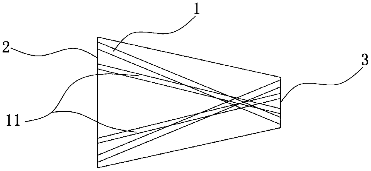
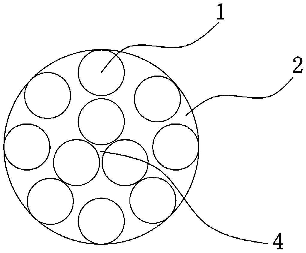
[0027] In order to achieve the purpose of the present invention, as Figure 2-4 As shown, in some embodiments of the fiber optic cone rod of the present invention, it includes a plurality of optical fiber filaments 1, and the plurality of optical fiber filaments 1 gather forward from the incident end 2 and cross, and the plurality of optical fiber filaments 1 are in the crossing area Continue to extend forward to form exit ends 3 (only a few are shown in the figure, but they can be densely arranged as required). In this embodiment, multiple optical fiber filaments are gathered and crossed forward from the incident end, and the multiple optical fiber filaments continue to extend forward in the intersecting area to form an outgoing end. Using the characteristics of crossing, each optical fiber filament The entrance and exit are no longer in on...


PUM


Abstract

The invention discloses an optical fiber tapered rod, which includes a plurality of optical fiber filaments, which are gathered forward from the incident end and intersect, and the plurality of optical fiber filaments continue to extend forward in the form of spreading in the intersecting area to form an output end . The present invention gathers and crosses a plurality of optical fiber filaments forward from the incident end, so that the individual light rays of the optical fiber filaments with strong light and the optical fiber filaments with weak light can be mixed after crossing, so as to realize the homogenization of strong and weak light At the same time, the utilization rate of the light energy of the cone rod is improved, thereby improving the light coupling efficiency of the cone rod.

Description

technical field [0001] The invention relates to an optical device, in particular to an optical fiber tapered rod. Background technique [0002] Optical fiber tapered rods have a very wide range of applications in the field of optoelectronics, such as figure 1 As shown, a plurality of optical fiber filaments 1 are gradually gathered together from the input end 2 to the output end 3 to form a tapered rod-like structure, which realizes the drawing effect on the optical fiber. [0003] Such as figure 1 As shown, in the current optical fiber taper, the positions of the entrance and exit of the optical fiber 1 are in one-to-one correspondence, so the direction of the light in each optical fiber travels independently. The first result of this method is that, The cone rod cannot have the effect of uniform light, and at the same time, the utilization rate of the light energy of the cone rod is low, thereby reducing the light coupling efficiency of the cone rod. Contents of the in...

Claims


Application Information

Patent Timeline
Patent Type & Authority Patents(China)
IPC IPC(8): G02B6/04
CPCG02B6/04
Inventor 杨西斌熊大曦
Owner SUZHOU INST OF BIOMEDICAL ENG & TECH CHINESE ACADEMY OF SCI
Learn More