Optical elements and projecting system including optical elements

A technology of optical components and projection systems, which is applied to optical components, optical components, electrical components, etc., can solve the problems of low optical coupling efficiency, insufficient light uniformity, uneven brightness of the projection screen, etc., and achieves the effect of reducing the number of components

Inactive Publication Date: 2008-10-01
HONG KONG APPLIED SCI & TECH RES INST
View PDF2 Cites 3 Cited by
  • Summary
  • Abstract
  • Description
  • Claims
  • Application Information

AI Technical Summary

Problems solved by technology

Since this light emitting device lacks a light mixing device, the uniformity of the light emitted by the collimating lens is not high enough, so that there will be problems of uneven brightness on the projection screen
The latter uses a tapered light guide to fully mix the light received from the LEDs to improve the uniformity of the light. However, the disadvantage of this device is that part of the light emitted by the LEDs will be lost and cannot fully enter the light guide, so its Low light coupling efficiency

Method used


Image

  • Optical elements and projecting system including optical elements
  • Optical elements and projecting system including optical elements
  • Optical elements and projecting system including optical elements

Examples


Embodiment Construction

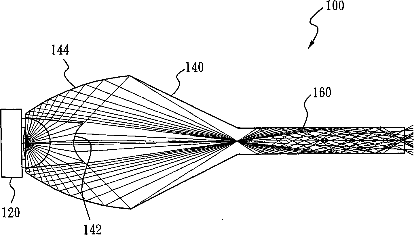
[0015] see figure 1 , figure 1 It is a cross-sectional view of a preferred embodiment in which the optical element of the present invention is applied to a light emitting device 100 . The light emitting device 100 includes a light source 120 and an optical element, wherein the optical element includes a light concentrating part 140 and a light guiding part 160 , and the light concentrating part 140 has a refraction surface 142 and a reflection surface 144 . In this embodiment, the light-condensing part 140 and a light-guiding part 160 can be integrally formed or composed of two components, and the light source 120 can be a light-emitting diode (for example: a white light-emitting diode), an array of light-emitting diodes ( For example: composed of red, green and blue light-emitting diodes) and emit light simultaneously or sequentially through control, the light source 120 can also be other light-emitting elements (such as: ordinary light bulbs or solid light-emitting devices)...


PUM


Abstract

The present invention provides an optical element and a projection system containing the optical element. The optical element includes a condensing part, the condensing part includes a reflecting surface and a refracting surface, used for condensing the light from the light source; and a light guide part, connected to the output end of the condensing part and evenly emitting the light condensed by the condensing part. The invention provides an optical element and a projection system, capable of improving more even brightness and more high light coupling efficiency.

Description

technical field [0001] The invention relates to an optical element, in particular to an optical element used in a projection system. Background technique [0002] As the use of projectors has become more and more common in recent years, not only the body of the projector has become thinner and thinner, but its performance has also been greatly improved. By improving the light-emitting device inside the projector, the brightness of the projectors currently on the market has improved a lot compared to the earlier products. When playing, you don't need to turn off the indoor light to get a clear projection effect. Currently, there are many ways to improve the light emitting device of a projector. For example, US Patent Publication Nos. 2005 / 0179041 A1 and 2006 / 0164607 A1 disclose different structures of the light emitting device to improve brightness or light uniformity. The former is to cover a collimating lens on the light-emitting diode. Since the light-emitting diode emits...

Claims


Application Information

Patent Timeline
Patent Type & Authority Applications(China)
IPC IPC(8): G03B21/14G03B21/00G02B6/00
CPCH04N9/3102H04N9/3152G03B21/14G02B19/0061G02B27/0916G02B19/0028G02B27/0994G02B17/0868G02B27/141H04N9/3197G03B33/12G03B21/2033G03B21/2066G03B21/208
Inventor 刘颖陈守龙
Owner HONG KONG APPLIED SCI & TECH RES INST
Why Eureka
Try Eureka