Beam combiner and laser comprising same

A beam combiner and optical fiber technology, applied in the field of lasers, can solve the problems of reduced power gain efficiency, affecting optical signals, and high gain efficiency, and achieve the effects of improving power bearing capacity, realizing high power transmission, and improving optical coupling efficiency.

Inactive Publication Date: 2017-05-31
深圳朗光科技有限公司
View PDF7 Cites 3 Cited by
  • Summary
  • Abstract
  • Description
  • Claims
  • Application Information

AI Technical Summary

Problems solved by technology

[0002] Fiber amplification and fiber lasers are current research hotspots. The current common solution is forward pumping. For fiber amplifiers or fiber lasers, the gain efficiency of forward pumping is low, and the protection requirements for the entire optical path are strict. For fiber amplifiers or fiber lasers, pumping has high gain efficiency and low protection requirements for the entire optical path
Regardless of forward pumping or reverse pumping, the optical signal needs to be transmitted through a beam combiner. The beam combiner for forward pumping mostly adopts a fiber melting structure, which will inevitably destroy the transmission characteristics of the fiber itself. In the pumping technology, the beam combiner includes an input collimator and an output collimator, the input collimator includes a pump fiber and an active fiber, the end faces of the pump fiber and the active fiber are provided with lenses, and the pump fiber and the Both the end face of the active fiber and the end face of the lens become reflective surfaces, which affect the transmission of optical signals, resulting in reduced power gain efficiency and serious signal attenuation. Moreover, the end face of the active fiber usually needs to be fused with a section of fiber to increase the pass through of the fiber core. The light area will also affect the transmission of the pump light, so that the conversion efficiency of the pump light will drop sharply; similarly, the output collimator also includes the optical fiber and the lens, and there is an interface between the two, and the entire beam combining More interfaces between the beam combiner increase the power density and reduce the withstand power of the beam combiner

Method used


Image

  • Beam combiner and laser comprising same
  • Beam combiner and laser comprising same
  • Beam combiner and laser comprising same

Examples


Embodiment Construction

[0021] In order to make the object, technical solution and advantages of the present invention clearer, the present invention will be further described in detail below in conjunction with the accompanying drawings and embodiments. It should be understood that the specific embodiments described here are only used to explain the present invention, not to limit the present invention.

[0022] The specific realization of the present invention is described in detail below in conjunction with specific embodiment:

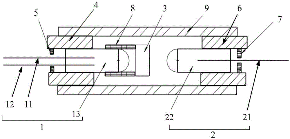
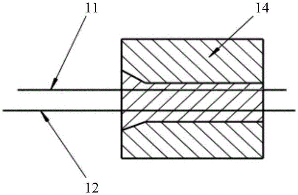
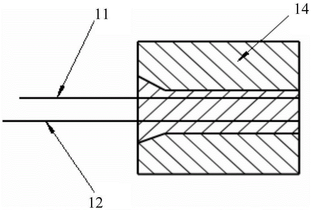
[0023] Please refer to figure 1 , the embodiment of the present invention provides a beam combiner, which is mainly used for devices such as reverse pumped fiber amplifiers and fiber lasers. The beam combiner includes a dual-fiber collimator 1, a single-fiber collimator 2, and an optical filter 3. The dual-fiber collimator 1 includes an input optical fiber 11 for transmitting pump light, an active optical fiber for optical amplification The optical fiber 12 and the firs...


PUM


Abstract

The present invention is suitable for the laser technology field, and provides a beam combiner. The beam combiner comprises a dual fiber collimator, a single fiber collimator and an optical filter. The dual fiber collimator comprises input fibers configured to transmit pump light, active fibers configured to perform light amplification and a first lens in non-interface welding with the end portions of the input fibers and the active fibers, wherein the welding end of the first lens is a plane, one end opposite to the welding end is a curve, the optical filter is arranged on the output light path of the curve, the pump light is reflected to the active fibers and transmits signal light, the single fiber collimator comprises output fibers and a second lens in non-interface welding with the end portion of the output fibers, and the non-welding end of the first lens is opposite to the non-welding end of the second lens. Because there is no interface between each fiber and each lens, there is no attenuation when the pump light and the signal light are transmitted between the fibers and the lens, and the optical coupling efficiency is high; the power bearing capacity is high, and the high-power transmission is realized; a fiber fusion-elongation technology is not employed, the fiber performance itself can be maintained, the pump conversion efficiency is high, and the product performance is stable.

Description

technical field [0001] The invention belongs to the technical field of lasers, in particular to a beam combiner and a laser including the beam combiner. Background technique [0002] Fiber amplification and fiber lasers are current research hotspots. The current common solution is forward pumping. For fiber amplifiers or fiber lasers, the gain efficiency of forward pumping is low, and the protection requirements for the entire optical path are strict. For fiber amplifiers or fiber lasers, pumping has high gain efficiency and low protection requirements for the entire optical path. Regardless of forward pumping or reverse pumping, the optical signal needs to be transmitted through a beam combiner. The beam combiner for forward pumping mostly adopts a fiber melting structure, which will inevitably destroy the transmission characteristics of the fiber itself. In the pumping technology, the beam combiner includes an input collimator and an output collimator, the input collimato...

Claims


Application Information

Patent Timeline
Patent Type & Authority Applications(China)
IPC IPC(8): G02B6/26
CPCG02B6/262
Inventor 李泉岳超瑜朱少军洪春权
Owner 深圳朗光科技有限公司
Why Eureka
Try Eureka