SC-type optical fiber connector

A technology for optical fiber connectors and connecting parts, which is applied in the coupling of optical waveguides and other directions, can solve the problems of affecting the optical coupling efficiency, uneven radial force, affecting the service life, etc., to improve the optical coupling efficiency and radial force. Uniform, extended service life effect

Active Publication Date: 2016-06-01
灏讯电缆连接器制造(常州)有限公司
View PDF6 Cites 3 Cited by
  • Summary
  • Abstract
  • Description
  • Claims
  • Application Information

AI Technical Summary

Problems solved by technology

[0004] However, this kind of optical fiber connector has the following defects in actual use: first, the concentricity of the first ferrule and the second ferrule is difficult to grasp when they are mated, which makes it difficult to fully couple the end faces of the pre-embedded optical fiber and the pigtail, Affect the optical coupling efficiency; second, because the above-mentioned connector needs to use the first ferrule to achieve mutual insertion with other connectors, and only the tail of the first ferrule is inserted in the tail handle, so that the tail handle is not connected to the first The support effect of the ferrule is poor, which leads to loosening of the first ferrule due to uneven radial force during the insertion and removal process, which affects the service life; This rigid clamping structure is not only inconvenient to disassemble and assemble, but also easy to damage the components due to excessive stress during the assembly process

Method used


Image

  • SC-type optical fiber connector
  • SC-type optical fiber connector
  • SC-type optical fiber connector

Examples


Embodiment Construction

[0022] The present invention will be further described below in conjunction with the accompanying drawings.

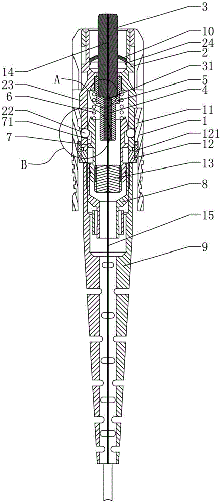
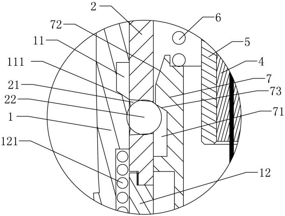
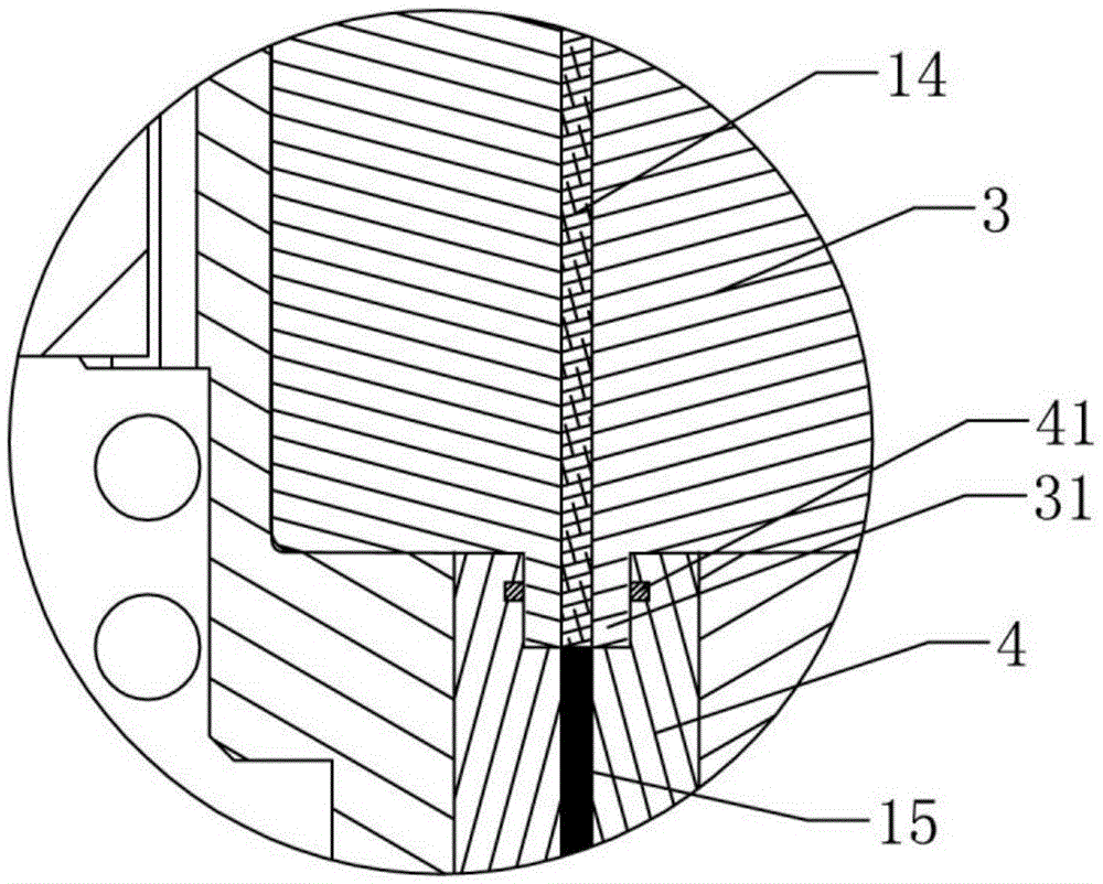
[0023] Such as Figure 1 to Figure 3 An SC-type optical fiber connector shown includes a package housing 1, a socket seat 2, a first ferrule 3, a second ferrule 4, a tail handle 5, a balance spring 6, a support seat 7, a ring nut 8 and The rubber sleeve 9, the socket seat 2 is sleeved in the packaging shell 1, the first ferrule 3 and the second ferrule 4 are inserted into the tail handle 5, the first ferrule 3, the second ferrule 4 and the tail The handle 5 is fixed by an adhesive to form a ferrule assembly. The tail handle 5 is sleeved in the sleeve seat 2, and the front end of the tail handle 5 is offset against the sleeve seat 2, and the front end of the support seat 7 extends into the sleeve seat 2. A balance spring 6 is connected between the tail handle 5 and the support seat 7, the ring nut 8 is sleeved on the rear end of the support seat 7, and the front end of...


PUM


Abstract

The invention discloses a SC-type optical fiber connector comprising a packaging housing, a sleeve seat, a first inserting core, a second inserting core, a tail handle, a balance spring, a bearing seat, a clamp screw nut, and a rubber sleeve pipe. The end part of the first inserting core is provided with a small diameter connecting part in an extended manner, and the corresponding end part of the second inserting core is provided with a connecting groove. The middle part of the first inserting core is connected with an elastic support, and the outermost edge of the elastic support abuts against the inner wall of the sleeve seat. The rear end outer wall of the sleeve seat is provided with an installation groove, in which is movably disposed a steel ball. The front end outer wall of the bearing seat is provided with an annular clamping groove. The inner wall of the packaging housing is provided with an annular avoiding groove cooperated with the steel ball, and the rear end of the sleeve seat is fixedly connected with a rear seat, and a reset spring is disposed between the rear seat and the packaging housing in an abutting manner. The middle part outer wall of the sleeve seat is provided with a large diameter part, and the packaging housing is movably disposed between the large diameter part and the rear seat. The SC-type optical fiber connector has advantages of simple and reasonable structure, convenient and fast installation, high optical coupling efficiency, stable working performance, and long service lifetime.

Description

technical field [0001] The invention relates to the technical field of optical fiber splicing devices, in particular to an SC type optical fiber connector. Background technique [0002] With the continuous development of optical communication technology, optical fiber into copper and fiber to the home are widely used, and fiber optic connectors are also widely used in the connection of optical fibers. Optical fiber connectors can be divided into: FC, SC, ST, LC, D4, DIN, MU, MT, etc. according to the structure of the connector. [0003] The structure of the SC-type optical fiber connector in the prior art usually includes a packaging shell, a sleeve seat, a first ferrule, a second ferrule, a tail handle, a balance spring, a support seat, a ring nut and a rubber sleeve, and the sleeve The seat is set in the package shell, the first ferrule and the second ferrule are inserted into the tail handle, the first ferrule, the second ferrule and the tail handle are fixed by adhesive...

Claims


Application Information

Patent Timeline
Patent Type & Authority Applications(China)
IPC IPC(8): G02B6/38
CPCG02B6/38
Inventor 施明博
Owner 灏讯电缆连接器制造(常州)有限公司
Why Eureka
Try Eureka