Sealing structure of powder box

A technology of sealing structure and powder box, which is applied in electrography, optics, instruments, etc. It can solve problems such as inconvenient operation, powder leakage, and poor adhesion effect, so as to maintain adhesion and scalability, easy operation, and high efficiency. fast effect

Inactive Publication Date: 2012-04-04
PRINT RITE UNICORN IMAGE PROD CO LTD OF ZHUHAI
View PDF4 Cites 7 Cited by
  • Summary
  • Abstract
  • Description
  • Claims
  • Application Information

AI Technical Summary

Problems solved by technology

The current common method is to use double-sided adhesive tape to cover the sponge strip between the metal surface of the powder scraper and the frame of the pow

Method used


Image

  • Sealing structure of powder box
  • Sealing structure of powder box
  • Sealing structure of powder box

Examples


Example Embodiment

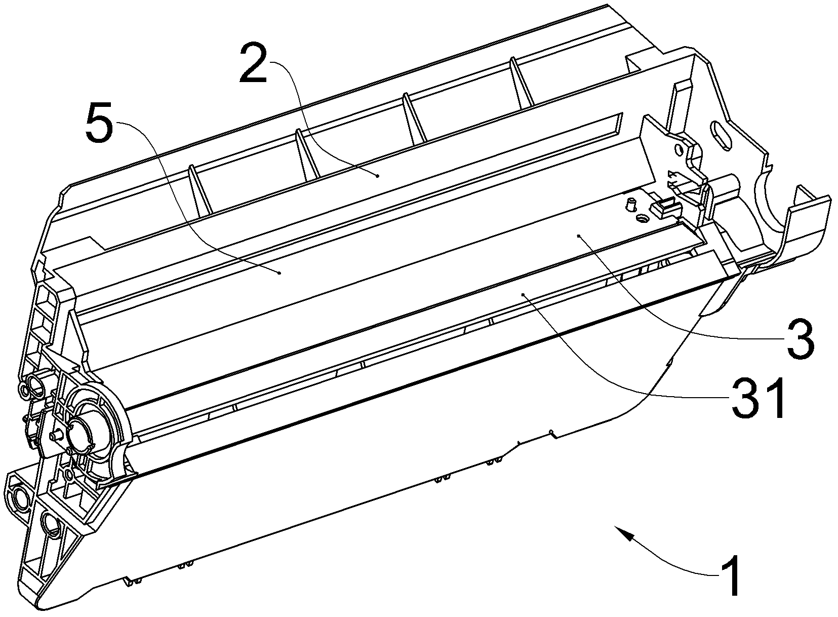
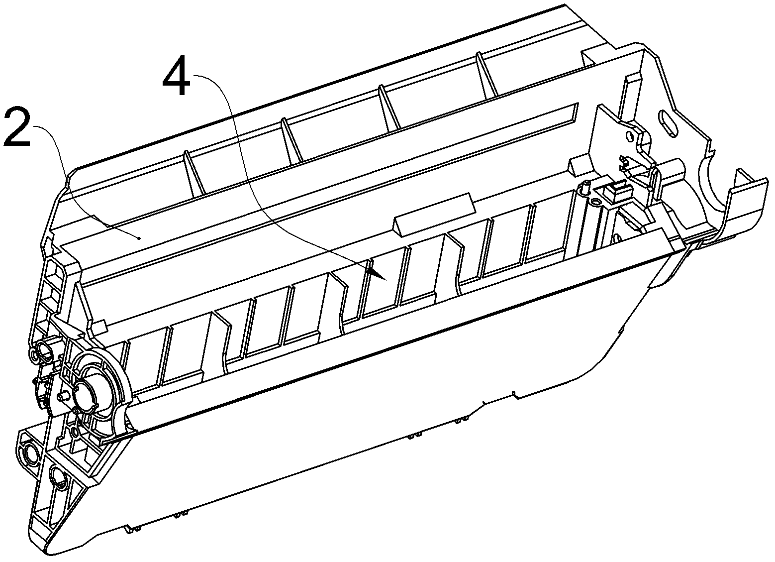
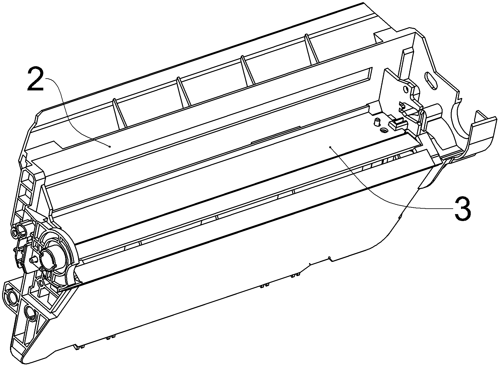
[0022] figure 1 Shown is a waste toner bin assembly 1 that adopts the powder box sealing structure of the present invention, see figure 2 and image 3 The waste toner bin assembly 1 includes a waste toner bin frame 2 and a cleaning scraper 3. The waste toner bin frame 2 has an opening 4 for recycling toner. The cleaning scraper 3 is fixed on the waste toner bin frame 2 by screws or other means. There are 4 openings. The waste toner bin frame 2 is a plastic part, and the cleaning scraper 3 is a metal part. The cleaning blade 3 is placed laterally at the opening 4 , and the lower edge 31 of the cleaning blade 3 is in contact with the unshown photosensitive drum, so as to scrape off the toner on the photosensitive drum and collect it into the waste toner bin frame 2 . In order to prevent the waste toner in the waste toner bin frame 2 from leaking between the waste toner bin frame 2 and the cleaning scraper 3, the junction of the waste toner bin frame 2 and the cleaning scrape...


PUM


Abstract

The invention provides a sealing structure of a powder box. The sealing structure comprises a powder box frame and a powder scraper, wherein the powder box frame has an opening; the powder scraper is positioned at the opening and fixed on the powder box frame; and a foaming sealing adhesive is filled into a joint part of the powder scraper and the powder box frame. The foaming sealing adhesive which is adopted in the sealing structure of the powder box can be filled into a part, required to be sealed, of the powder box, and can foam in place, and automatic operation can be realized; adjustment of the conventional production process sequence is not required during implementation of the sealing structure; only the conventional sponge adhesion process is replaced, and efficiency is higher; the adhesive is only required to be filled in the sealed part without great effort on sponge adhesion, so the sealing structure is easy to operate; and the foaming sealing adhesive can keep adhesiveness and flexibility for a long time and keep the best sealing effect for a long time.

Description

technical field [0001] The invention relates to a sealing structure of a powder box. Background technique [0002] Laser printers are currently one of the most widely used external computer output devices, which use the physical and chemical principles of light, electricity, and heat to output text or images through interaction. The basic process can be divided into seven steps: charging, exposure, development, transfer, fixing, cleaning, and power elimination. First, the surface of the photosensitive drum is uniformly charged by the charging roller. The laser scanner emits modulated laser light containing image information to the photosensitive drum, forming an electrostatic latent image corresponding to the image to be copied on the surface of the photosensitive drum. Next, toner from the developer roller is in turn attracted to the surface of the photosensitive drum to convert the electrostatic latent image into a visible image. With the rotation of the photosensitive ...

Claims


Application Information

Patent Timeline
IPC IPC(8): G03G15/08
CPCG03G15/0812G03G15/0898G03G15/08
Inventor 苏健强周巍峙
Owner PRINT RITE UNICORN IMAGE PROD CO LTD OF ZHUHAI
Why Eureka
Try Eureka