Coupling structure for a surgical instrument

A connection structure and surgery technology, applied in surgery, joints, applications, etc., can solve the problems of no extra space for robotic arms, mutual collision or interference of instruments, narrow distance between instruments and adapters, etc., and achieve free and smooth robot surgery Effect

Active Publication Date: 2012-04-04
EATON CORP
View PDF6 Cites 15 Cited by
  • Summary
  • Abstract
  • Description
  • Claims
  • Application Information

AI Technical Summary

Problems solved by technology

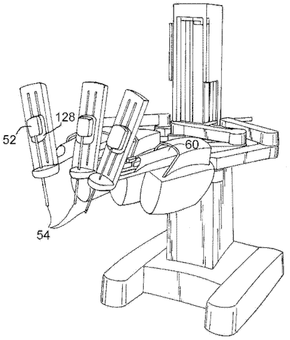
[0007] However, in the conventional instrument connection structure, the width of the adapter is also wide due to the wide case. Therefore, when multiple instruments are installed on multiple robotic arms, the instruments may collide or interfere with each other.
[0008] In addition, in the conventional connection structure, the distance between the instrument and the adapter is very narrow because the housing is mounted close to the adapter. The upper space of the surgical site does not have extra space for installing other surgical instruments other than the robot arm (and instruments), so there is a limitation that the surgical behavior is restricted

Method used


Image

  • Coupling structure for a surgical instrument
  • Coupling structure for a surgical instrument
  • Coupling structure for a surgical instrument

Examples


Embodiment Construction

[0042] The present invention can be changed in many ways, and can have various embodiments, and the specific embodiments are shown in the drawings and described in detail. However, this does not limit the present invention to specific embodiments, and it should be understood that all changes, equivalents, and substitutions included in the spirit and technical scope of the present invention are included. When describing the present invention, detailed descriptions related to known techniques may obscure the gist of the present invention, and the detailed descriptions will be omitted.

[0043] Various constituent elements may be described using terms such as "first", "second", etc., but the constituent elements are not limited by the terms. The terms are used only for the purpose of distinguishing one constituent element from another constituent element.

[0044] The terms used in the present application are used to describe specific embodiments only, and are not intended to limi...


PUM


Abstract

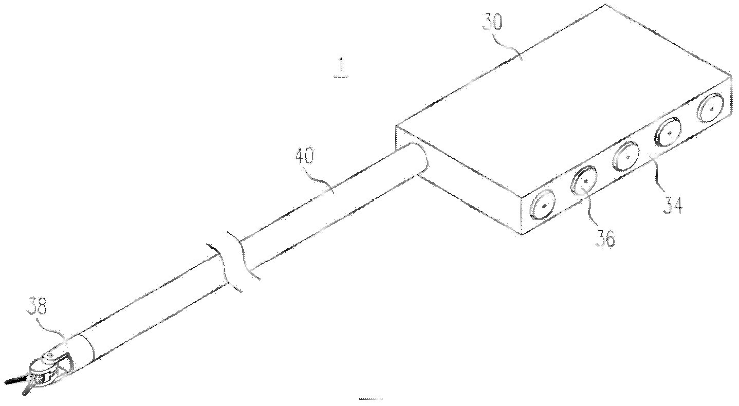
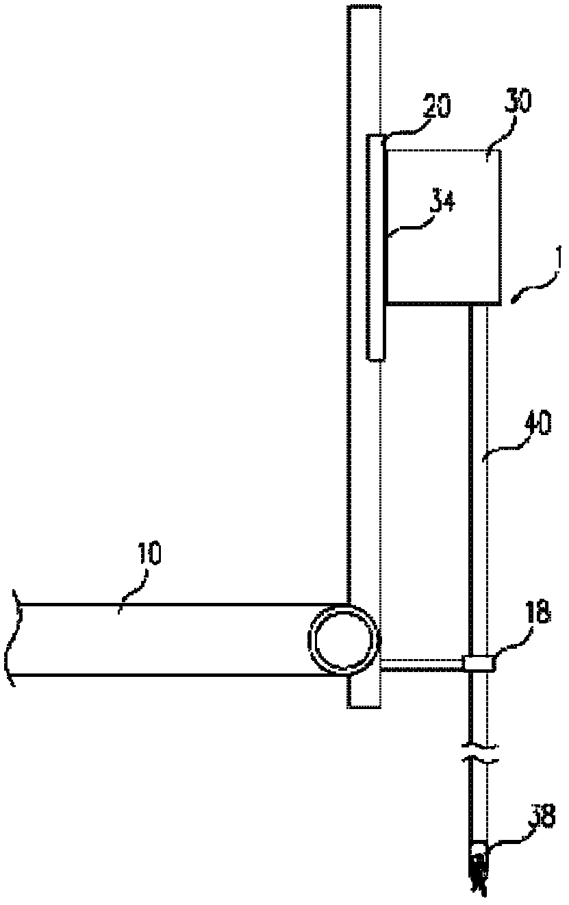
Disclosed is a coupling structure for a surgical instrument. The coupling structure for mounting a surgical instrument onto an adapter arranged at the front end of a robot arm comprises: a housing formed into a tablet shape with a predetermined thickness and mounted on the front end of the robot arm; an interface unit formed in the thickness portion of the housing and coupled to the adapter; a plurality of drivers mounted on the interface unit to be actuated by the driving force transmitted by the adapter; a shaft coupled to the housing and accommodating a power transmission means, which is connected to the drivers, therein; and an effector coupled to the end of the shaft and connected to the power transmission means to perform operations required for surgery in accordance with the operation of the drivers.; The housing of the instrument is formed into a slim tablet shape and the interface unit is formed in the thickness portion of the housing, to thereby minimize collisions or interference among instruments even when the instruments are mounted on the respective robot arms.

Description

technical field [0001] The present invention relates to a connection structure of surgical instruments. Background technique [0002] Medical surgery refers to the means of using medical instruments to incise, cut or manipulate skin, mucous membranes or other tissues to cure diseases. In particular, laparotomy, in which the skin of the surgical site is incised to treat, reshape, or remove the internal organs, etc., has recently become an alternative to surgery using robots due to problems such as bleeding, side effects, patient pain, and scars. Very popular. [0003] This surgical robot includes a master robot and a slave robot. The master robot and the slave robot can be configured as a whole or as a separate device and arranged in the operating room. The master robot generates the required signals through the operation of the doctor and performs Transmission, the slave robot receives signals from the master robot and directly performs operations on the patient. [0004]...

Claims


Application Information

Patent Timeline
Patent Type & Authority Applications(China)
IPC IPC(8): A61B17/00A61B19/00B25J17/00
CPCA61B19/2203A61B2017/00477A61B34/30A61B17/00
Inventor 崔胜旭元钟硕
Owner EATON CORP
Why Eureka
Try Eureka