Method for manufacturing thin-film magnetic recording medium

a technology of magnetic recording medium and manufacturing method, which is applied in the direction of magnetic recording layer, record information storage, instruments, etc., can solve the problems of further damage and stress on the concentrator, damage to the head or the magnetic recording medium 7 (or both), and reduce the process time. , the effect of reducing production waste and improving quality control

Inactive Publication Date: 2002-03-07
FUJI ELECTRIC CO LTD
View PDF10 Cites 12 Cited by
  • Summary
  • Abstract
  • Description
  • Claims
  • Application Information

AI Technical Summary

Benefits of technology

0066] It should be understood that conventional manufacturing methods polish a surface of the laminate in air with a tape and burnish the surface of an as-coated lubricant layer with a tape or with a head. Remaining surface defects from tape-polishing frequently cause missing signals and electronic errors. The present invention eliminates this concern, and all physical polishing concerns, by dry plasma etching or other non-physical treatment of carbon protection layer 5. The present invention omits the step of burnishing the surface of a lubricant layer, reduces process time, easily improves quality control, and minimizes production waste.
0067] The present invention facilitates removal of particles and micro protrusions on carbon protection layer 5 under vacuum conditions without requiring additional complicated and costly production steps. The present invention facilitates stabilizing the flight of a magnetic head, not shown. The present invention also stabilizes quality control in manufacturing thin-film magnetic recording media, reduces error-rates, costs and increases mass productivity.
0068] Additionally, hard disk drives including thin-film magnetic recording mediums manufactured according to the present invention are highly reliable and minimize errors, missing signals, and collision of the magnetic head (not shown).

Problems solved by technology

This causes either the head or the magnetic recording medium 7 (or both) to be damaged.
Unfortunately, any conventional manufacturing method that includes the step of tape-polishing, are necessarily rolls particles in and on the surface of the carbon protection layer, thereby damaging the surface of the carbon protection layer and causing further damage and stress concentrators.
During the step of cleaning the carbon protection layer in the air, oxidation, nitridation, water absorption, and other chemical and physical problems are caused in the surface of the carbon protection layer by exposure to air before the step of coating the lubricant layer.
As a result, the surface of the carbon protection layer is modified, the adhesion of the carbon protection layer and the lubricant layer is adversely affected and the quality of the magnetic recording medium is greatly impaired.

Method used


Image

  • Method for manufacturing thin-film magnetic recording medium
  • Method for manufacturing thin-film magnetic recording medium
  • Method for manufacturing thin-film magnetic recording medium

Examples


first embodiment

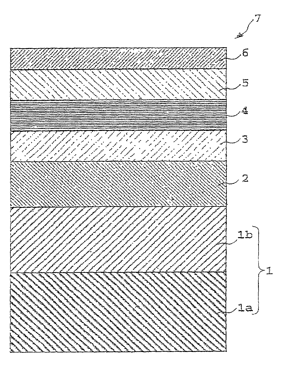
[0089] Thin-film magnetic recording medium 7, resting on plasma-etched carbon protection layer 5, adopts the smooth surface, is not thereafter damaged and greatly reduces missing signal errors. Such a dramatic benefit may be attributed to the surface of thin-film magnetic recording medium 7, since there is no trace of polishing and initial application is on a smooth surface, and to the other dramatic effects of the present invention. As a result, it is not necessary to conduct burnishing after forming lubricant layer 6. This greatly reduces time and production costs and substantially prevents missing signal errors and collision of the magnetic head.

second embodiment

[0090] Second Embodiment

[0091] Thin film magnetic recording medium 7, is manufactured in the same way as in the first embodiment except that the process gas for vacuum plasma etching is a mixture of Ar, O.sub.2 and N.sub.2 where the mixing ratio thereof is approximately 6:1:3.

[0092] After etching carbon protection layer 5, the particles on the as-etched carbon protection layer 5 are counted before coating lubricant layer 6 as in the first embodiment. The results are described in FIG. 4 and designated by the letter E below the horizontal axis of the figure.

[0093] The missing signal errors are measured on magnetic recording medium 7 according to the second embodiment in the same way in the first embodiment. The average number of missing signals is 4.0 pulses per a surface and is shown by the letter E in FIG. 4.

[0094] It is clear that even with a process gas different from that of the first embodiment, thin-film magnetic recording medium 7 is as good as in the first embodiment.

third embodiment

[0095] Third Embodiment

[0096] Thin-film magnetic recording medium 7, according to a third embodiment of the invention, is manufactured in the same way as in the first embodiment except that the surface of carbon protection layer 5 is etched by DC plasma etching with oxygen ions for 3 sec under the following conditions. The electrode facing opposite to the laminate, having carbon protection layer 5, is a carbon electrode, having a DC voltage of -300 V applied. A process gas for the DC plasma etching is a mixture of Ar and O.sub.2, having a ratio of about 9:1. A bias voltage of +100 V is applied to the laminate.

[0097] After etching carbon protection layer 5, the particles on the as etched carbon protection layer are counted before coating the lubricant layer in the same way as described in connection with the first embodiment. The results are designated by the letter F in FIG. 4.

[0098] Missing signal errors are measured on magnetic recording medium 7 according to the third embodiment ...


PUM

PropertyMeasurementUnit
thicknessaaaaaaaaaa
thicknessaaaaaaaaaa
diameteraaaaaaaaaa

Abstract

A thin-film magnetic recording medium is produced by forming a laminate for magnetic data recording on a nonmagnetic substrate through a dry process, forming a protection layer on the laminate also through a dry process, plasma-etching the protection layer, and forming a lubricant layer on the plasma-etched protection layer. All steps are completed continuously in a vacuum without abrasion. The surface of the resulting recording medium is substantially smoother than the prior art.

Description

[0001] 1. Field of the Invention[0002] The present invention relates to a method for forming a thin-film magnetic recording medium. More particularly, the present invention relates to a method for forming a thin-film magnetic recording medium that facilitates removing foreign particles from a surface of an as-formed protection layer without damaging the protection layer, thereby minimizing signal error.[0003] 2. Description of the Related Art[0004] A conventional thin-film magnetic recording medium (hard disk) is disclosed in Japanese Unexamined Laid Open Patent Application No. 2000-200409. This reference discloses a laminate structure including a Cr alloy undercoating layer on a substrate, a Co--Cr alloy nonmagnetic intermediate layer on the undercoating layer, a Co alloy magnetic recording layer on the intermediate layer, a protection layer made mainly of carbon on the magnetic recording layer and a lubricant layer on the carbon protection layer. Many conventional thin-film magnet...

Claims


Application Information

Patent Timeline
Patent Type & Authority Applications(United States)
IPC IPC(8): C23C16/56C23C14/58G11B5/84G11B5/85G11B5/851
CPCG11B5/84
Inventor ISHIBASHI, SINICHIIWAMA, TOSHINORITERASHIMA, EIJIKUBOTA, MASAOKOBAYASHI, YUJI
Owner FUJI ELECTRIC CO LTD
Why Eureka
Try Eureka