
Phase sequence judging circuit based on asymmetrical three-phase circuit theory
A three-phase circuit and phase sequence judgment technology, which is applied in the direction of phase sequence/synchronous indication, can solve the problems of inconvenient operation, accuracy, unsatisfactory reliability and circuit cost, etc., and achieve the effect of easy implementation
- Summary
- Abstract
- Description
- Claims
- Application Information
AI Technical Summary
Problems solved by technology
Method used
Image

Examples
Embodiment Construction
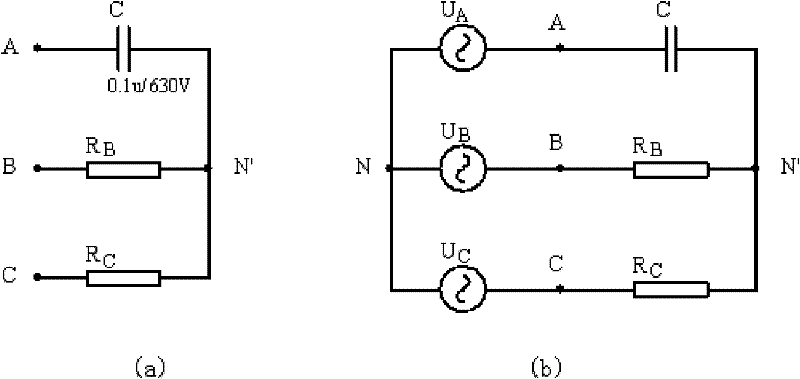
[0015] Asymmetrical three-phase circuits such as figure 1 As shown in (a), the figure assumes that:
[0016] X C = 1 ωC = R B = R C = R ( = 1 G )
[0017] G is the admittance, since X C It is a capacitive reactance, so the circuit load is asymmetrical, and the circuit is further transformed into a phase voltage source symmetrical (load asymmetrical) circuit, such as figure 1 (b) shown.
[0018] figure 1 The neutral point voltage in (b) (that is, the voltage between the neutral point of the load and the neutral point of the power supply) is
[0019] U · N , N ...
PUM
 Abstract
Description
Claims
Application Information