Optical fiber composite insulator

A fiber composite and insulator technology, applied in the direction of lead-in/through-type insulators, fiber mechanical structures, etc., can solve the problems of easy fiber breakage, lower insulator pass rate, and increased fiber loss, and achieve the effect of improving pass rate

Inactive Publication Date: 2012-04-11
JIANGSU SHENMA ELECTRIC CO LTD
View PDF5 Cites 18 Cited by
  • Summary
  • Abstract
  • Description
  • Claims
  • Application Information

AI Technical Summary

Problems solved by technology

Because the thermal expansion coefficients of the organic insulating material used for sealing potting, the insulating tube, and the optical fiber are quite different, the thermal expansion of the organic insulating material will cause stress in the hollow insulator when heated, thereby increasing the loss of the opti

Method used


Image

  • Optical fiber composite insulator
  • Optical fiber composite insulator
  • Optical fiber composite insulator

Examples


Embodiment Construction

[0008] In order to further illustrate the present invention, a preferred embodiment is given in detail as follows in conjunction with the accompanying drawings:

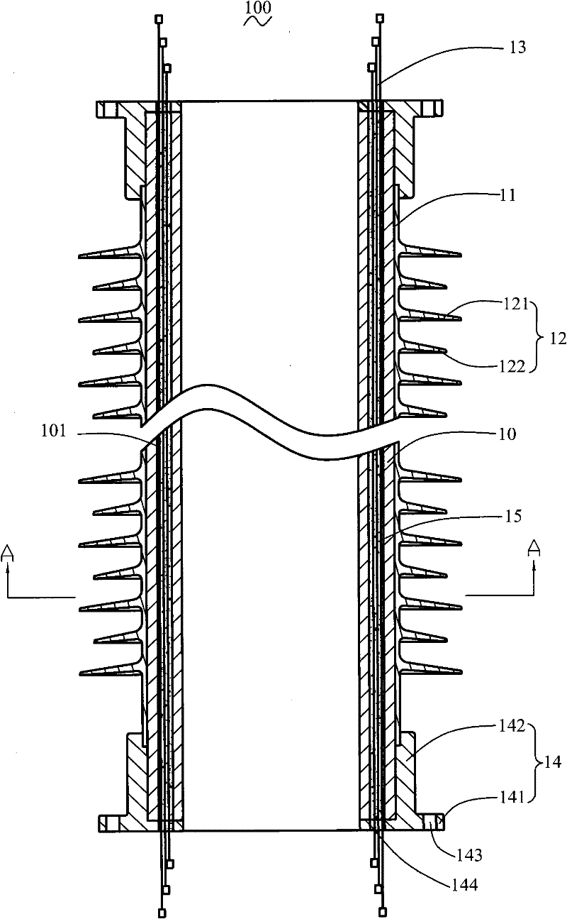
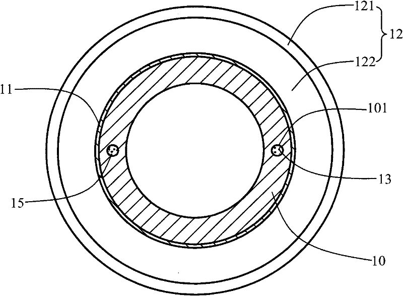
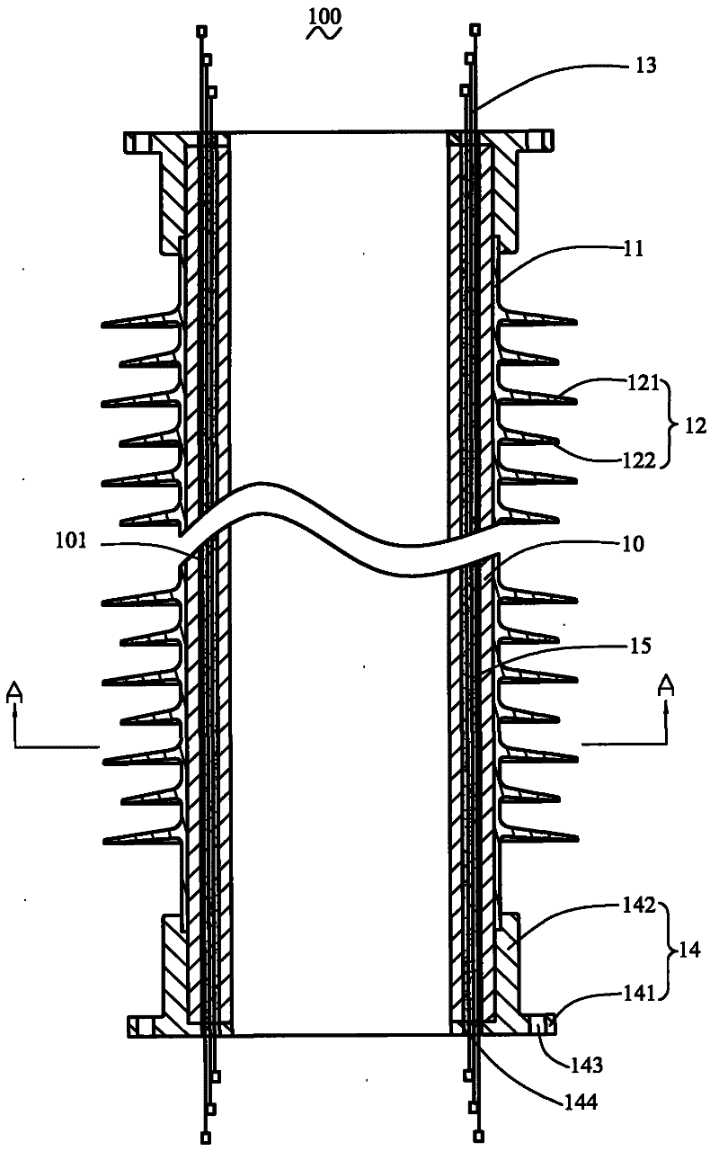
[0009] see figure 1 and figure 2 , which is a schematic structural diagram of an optical fiber composite insulator 100 provided by the present invention. The fiber optic composite insulator 100 includes a support body 10, a sheath 11 covering the outside of the support body 10, at least one shed 12 arranged on the sheath 11, at least one shed 12 arranged on the support body 10 The optical fiber 13 in the support body 10, at least one flange 14 arranged at one end of the support body 10, and the fixing glue 15 for fixing the optical fiber 13.

[0010] The support body 10 can be a solid insulator or a hollow insulating tube. When the support body 10 is a solid insulator, the optical fiber composite insulator 100 is a pillar composite insulator for supporting wires and preventing current from returning to ground. W...


PUM


Abstract

The invention relates to an optical fiber composite insulator, comprising a support body, wherein the support body comprises at least one through hole formed on the support body, the through hole is formed along the axial direction of the support body; and the optical fiber composite insulator also comprises at least one optical fiber penetrating through the through hole. Because the support body of the optical fiber composite insulator is provided with the through hole and the optical fiber is arranged in the through hole, a shed and a flange outside an insulating tube can be prefabricated and inserted, and then the optical fiber is fixed, thereby avoiding damaging the optical fiber when the shed is formed at high pressure and high temperature, and improving the percent of pass of the optical fiber composite insulators.

Description

technical field [0001] The invention relates to electric power equipment, in particular to an optical fiber composite insulator used in high-voltage electrical appliances in the electric power industry. Background technique [0002] The traditional high-voltage current measurement method is to use an electromagnetic transformer based on the principle of electromagnetic induction to measure the current. However, with the continuous increase of power capacity and voltage level, the traditional electromagnetic transformer presents insurmountable problems. In large-capacity, ultra-high-voltage power systems, traditional electromagnetic transformers will cause severe distortion of measurement results. However, due to the high transmission efficiency, stable performance and accurate measurement of optical fiber transmission current signal, the traditional electromagnetic current transformer is gradually replaced by the optical fiber transformer based on optical principle. In this...

Claims


Application Information

Patent Timeline
IPC IPC(8): H01B17/26G02B6/44
Inventor 马斌张鑫鑫
Owner JIANGSU SHENMA ELECTRIC CO LTD
Why Eureka
Try Eureka