Coolant circuit

A main cooling circuit, coolant technology, applied in the control of coolant flow, liquid cooling, engine cooling, etc., can solve problems such as limitation, difficulty in reaching engine operating temperature, and circuit control deterioration.

Active Publication Date: 2012-04-11
AUDI AG
View PDF8 Cites 19 Cited by
  • Summary
  • Abstract
  • Description
  • Claims
  • Application Information

AI Technical Summary

Problems solved by technology

[0006] The disadvantage of this type of engine cooling system is that the structure of the rotary valve imposes restrictions on the switchable circuits
The introduction of other loops will inevitably cause the control of individual loops to deteriorate
As a result, it is no longer possible to adjust the coolant temperature to the desired value with sufficient precision and speed, which makes it more difficult to reach the operating temperature of the engine

Method used


Image

  • Coolant circuit
  • Coolant circuit
  • Coolant circuit

Examples


Embodiment Construction

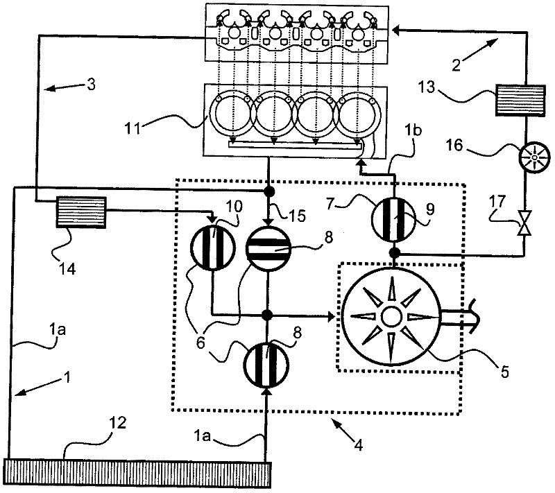
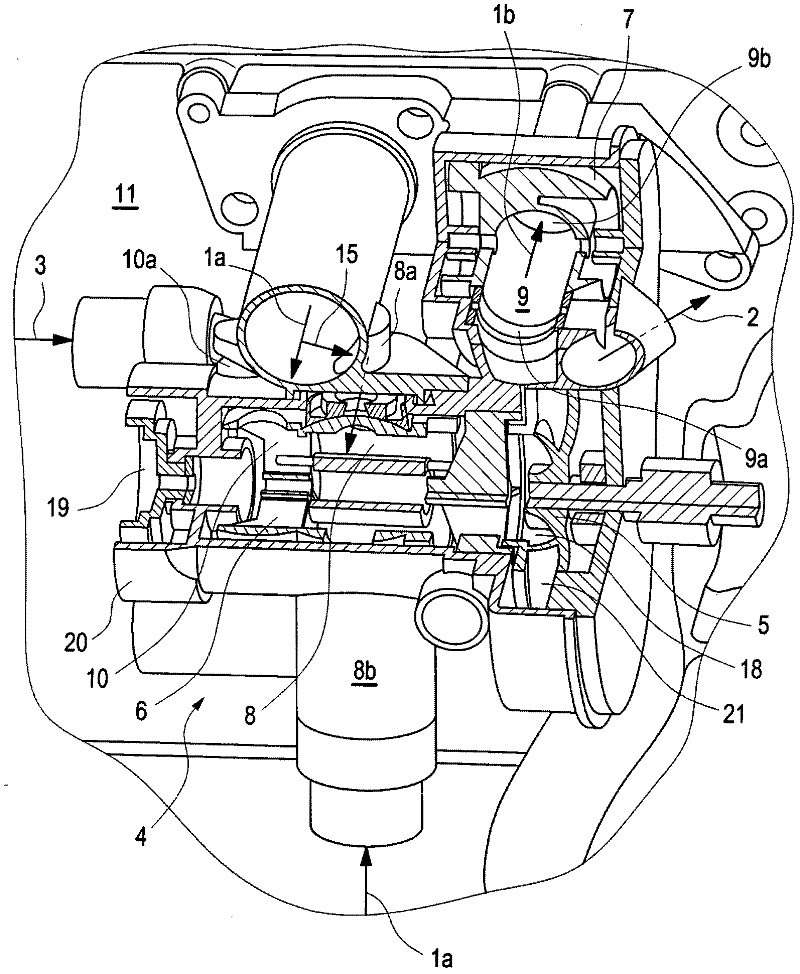
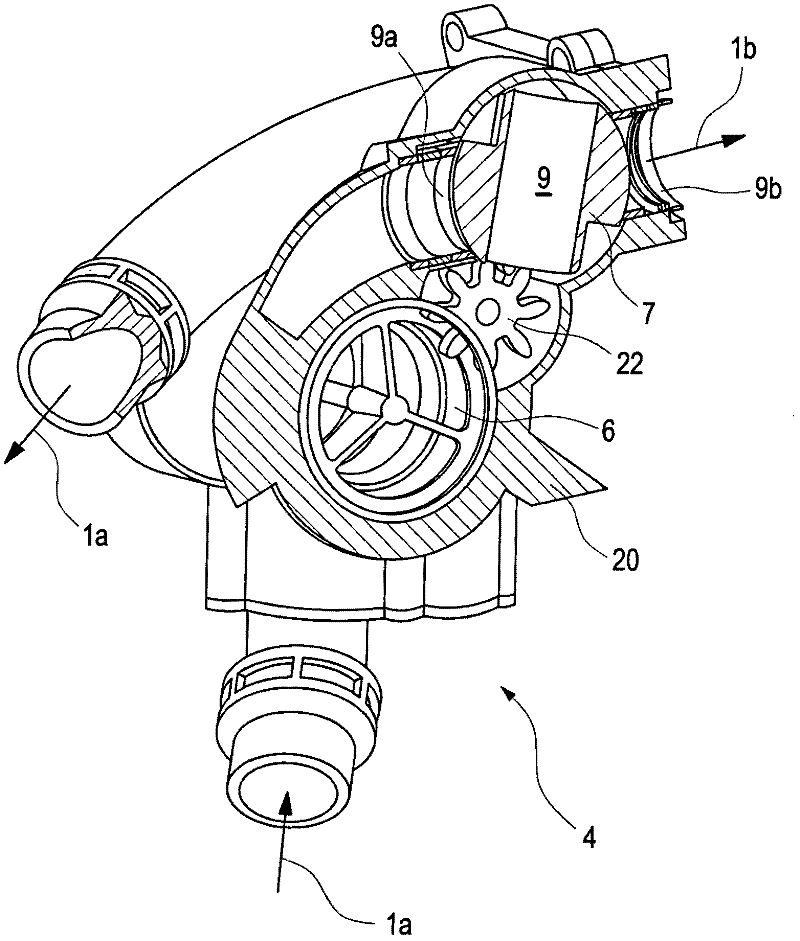
[0030] according to figure 1 , the coolant circuit for the engine 11 has a main cooling circuit 1 , a heating circuit 2 , an oil cooler circuit 3 and a rotary regulator 4 for controlling the coolant flow into each sub-circuit. The rotary regulator 4 comprises a rotary slide valve housing together with a rotatably mounted first rotary slide valve 6 and a second rotary slide valve 7 which have a rotary slide valve through-opening 8, 9 and 10. The rotary slide valve housing has in its wall a plurality of ports through which coolant can flow, which ports are at least partially connected to the rotary slide valve through-openings 8, 9 and and / or 10 intersect to form different flow paths for the connected partial circuits 1 , 2 and 3 . A coolant supply pump 5 is arranged on the rotary regulator 4 , which sucks in coolant from the first rotary slide valve 6 and feeds it into the second rotary slide valve 7 . The engine 11 essentially consists of a cylinder block and a cylinder hea...


PUM


Abstract

A coolant circuit, particularly a coolant circuit comprising a plurality of partial circuits 1, 2 and 3 of an internal combustion engine 11 having a main coolant circuit 1 and a heating circuit 2, and a coolant delivery pump 5 disposed at a rotating actuator 4, wherein the rotating actuator 4 comprises a rotary slide housing 20 having a plurality of connections 8a, 8b, 9a, 9b, 10a through which a coolant can flow, and a first and at least one second rotary slide 6 and 7 which is rotatably mounted in the rotary slide housing 20 and has at least one rotary slide flow opening 8, 9, 10 forming a flow path, and wherein the connections 8a, 8b, 9a, 9b, 10a can be brought into an at least partial overlap with the rotary slide openings 8, 9, 10 by a rotating movement of the respective rotary slide 6 and / or 7, wherein a first branch 1a of the main coolant circuit 1, which leads from the internal combustion engine 11 via a main cooler 12 to the main cooler connection 8b of the first rotary slide, can be controlled by the first rotary slide 6, and a second branch 1b of the main coolant circuit 1, which leads from an outlet 21 of the coolant delivery pump 5 to the internal combustion engine 11, can be controlled by the second rotary slide 7.

Description

technical field [0001] A coolant circuit of a motor vehicle engine with a plurality of subcircuits has devices for the operation of this coolant circuit, in particular for controlling the flow of coolant into the individual subcircuits. Background technique [0002] Coolant circuits of this type are preferably used for thermal management of the engine, wherein the coolant flow is distributed between the sub-circuits of the coolant circuit by means of operating the coolant circuit in such a way that the engine is regulated as quickly as possible optimized operating temperature. [0003] DE 602 09 019 T2 discloses a control valve for an engine cooling circuit through which coolant flows and has a first branch comprising the engine cooling system, a second branch forming a cooler branch line and a or a plurality of third branches each with at least one hot air generator for heating the passenger compartment. The control valve is configured as a base body having a fluid inlet,...

Claims


Application Information

Patent Timeline
Patent Type & Authority Applications(China)
IPC IPC(8): F01P7/14
CPCF01P2060/04F01P5/10F01P2037/02F04B49/00F16K5/10F01P7/14F01P2060/08F01P3/20
Inventor S·特里贝D·拉赫纳S·兰克S·亚当
Owner AUDI AG
Why Eureka
Try Eureka